Advertisement
Quick Links
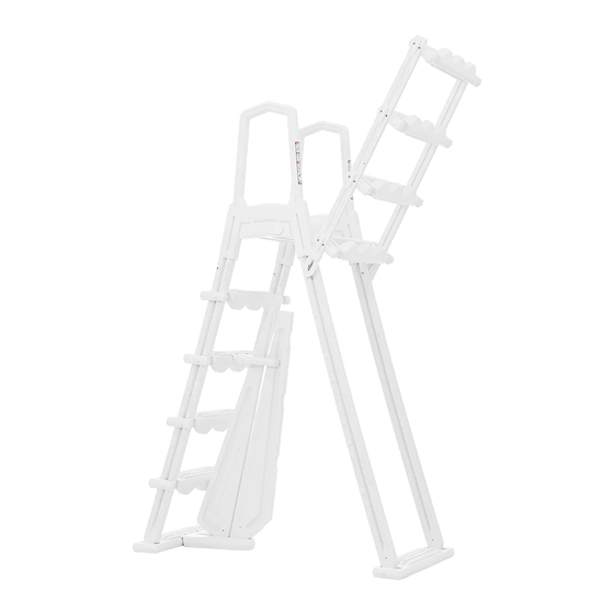
A-FRAME ABOVE GROUND POOL LADDER
ITEM# 75136
'
)
OWNER'S MANUAL AND SAFETY INSTRUCTIONS
SAVE THIS MANUAL. KEEP THIS MANUAL FOR SAFETY WARNINGS, PRECAUTIONS, ASSEMBLY,
OPERATION, INSPECTION, MAINTENANCE AND CLEANING PROCEDURES. WRITE THE PRODUCT'S
SERIAL NUMBER ON THE BACK OF THE MANUAL. OR THE MONTH AND YEAR OF PURCHASE IF
PRODUCT HAS NO SERIAL NUMBER
FOR QUESTIONS, PLEASE CALL CUSTOMER SERVICE: 909.628.0880
Advertisement

Related Manuals for XtremepowerUS 75136

Summary of Contents for XtremepowerUS 75136
- Page 1 A-FRAME ABOVE GROUND POOL LADDER ITEM# 75136 OWNER'S MANUAL AND SAFETY INSTRUCTIONS SAVE THIS MANUAL. KEEP THIS MANUAL FOR SAFETY WARNINGS, PRECAUTIONS, ASSEMBLY, OPERATION, INSPECTION, MAINTENANCE AND CLEANING PROCEDURES. WRITE THE PRODUCT'S SERIAL NUMBER ON THE BACK OF THE MANUAL. OR THE MONTH AND YEAR OF PURCHASE IF PRODUCT HAS NO SERIAL NUMBER FOR QUESTIONS, PLEASE CALL CUSTOMER SERVICE: 909.628.0880...
- Page 3 Remove the A-Frame ladder and its accessories from the box and check whether all the accessories are complete. First place the bottom tread on a flat surface with the grooved side facing up; then snap the two holders into the groove. Note: The two holders need to be snapped into the groove in the same direction.
- Page 4 4. AAffix the left and right fixing strips with bolt & gasket ( M6), and nut M6*85, donot over tighten (the accessories are in screw kit 5862050002 ) Gasket bolt Left fixing strip Right fixing strip 5. Use the 10x1-1/4 screws to affix the other three treads. Then put aside for later. Fix the treads to the left and right fixing strips with screws.
- Page 5 7. Affix the treads to the holders with screws with #10x1-1 / 4 . Fix the tread to holder with screws 8. Place the Lower Base on a level surface. Snap the front barrier into the groove on the lower base facing round edge. Snap the back barrier into the groove on the lower base facing the straight side.
- Page 6 10. Affix the lower base of the entrapment barrier into bottom step of the Inside portion of the Ladder with 2 pieces10 x 1-1/4# screws. Affix the barrier onto 10. Fix lower base of entrapment barrier into bottom step of the Inside portion of these two positions.
- Page 7 12. The ladder is designed to fit multiple pool heights. If your pool height is 52", locate the first line on the handrail of the ladder. Using a hacksaw, cut the handrail evenly through both sides. 52" Cut line If the pool height is 48", locate the second line on the handrail. Using a hacksaw, cut the handrail evenly through both sides.
- Page 8 13. Using a funnel, fill both holders with sand. Use approximately 20 Lbs. of sand in each holder. The barrier in step 11 have the front and back barrier. Fill holder with sand using a funnel 14. Assemble the handrails to the platform. Center the cover cap opening on the side of the handrail when the platform was just attached.
- Page 9 16. Secure all handrails to the legs with #10 1-1/4# screws Pushing them down over the Screw holders Step 16 Step 15 Place the ladder inside the pool where you want to enter and exit. The entrapment barrier should be inside of the pool. Once the ladder is placed in the pool, tip the ladder forwards and backwards and side to side to release any air that may be trapped inside.
- Page 10 The A-Frame ladder must be fixed on the edge of the pool. First, align the two holes on the surface of the deck platform with the edge of the pool, mark the hole positions at the edge of the pool with a fine marker pen, then drill through the edge of the swimming pool with a 5 / 16 "drill bit, and finally use bolts, nuts and washers to fix the ladder on the edge of the swimming pool.
- Page 11 Parts List Description Specification Application 48 -54 height above ground pool Weight limit 250 lbs Material Polythene 42" x 25" x 77" Products Size Gross Weight 24" x 8" x 60" Package Size Product Diagram and Accessories...
- Page 12 Part Number Description 47155001 Handrail 48850112 Cover Cap 47155011 Deck Platform 47155005 Holder 47155002 Tread 47155008 Bottom Tread 47155003 Upper Brace 47155009 Front Barrier 47155010 Back Barrier 47155004 Lower Base 47155007 Left Fixing Strip 47155006 Right Fixing Strip 5862050001 Screw Kit 5%Bolt! 5862050000 Screw Kit 2.5%Bolt! 5862050002...
Need help?
Do you have a question about the 75136 and is the answer not in the manual?
Questions and answers