Advertisement
Quick Links
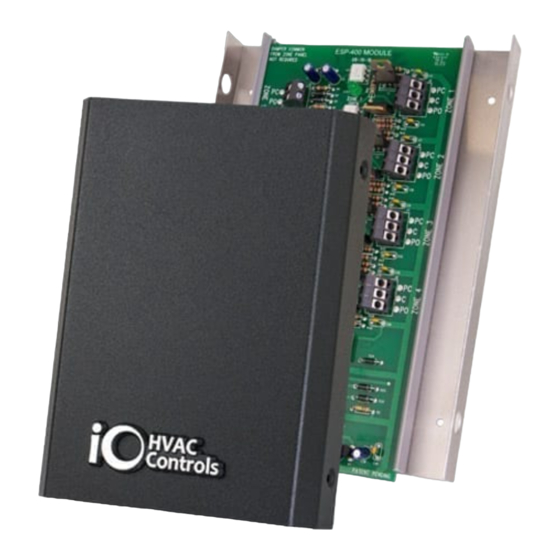
ESP-400 Electronic Static Pressure Module
INTRODUCTION
The ESP-400 is designed to work with any forced air zone control system capable of using
conventional 24 Volt, 3-wire, floating point, motorized zone dampers. The module will handle up to four
zones. The same transformer used to power the zone control panel is also used to provide power to
the ESP-400. The module uses a ESP-400-PS pressure sensor that is installed in the main discharge
air plenum of the HVAC system.
SEQUENCE OF OPERATION
As zone dampers open and close, the ESP-400 continuously monitors the system static pressure and
if required, sends a signal to zone dampers that are in the closed position to open to a point where the
proper static pressure level is maintained. The small amount of air that is allowed to bleed into non-
calling zones eliminates air noise and assures proper airflow through the HVAC system preventing coil
freeze up.
INSTALLATION
1. Make sure all power is disconnected to the HVAC equipment and zoning panel.
2. Remove the ESP-400 cover and locate the panel on a flat, non-condensating, vertical surface near
the zone control panel that will facilitate ease of access and wiring. Use appropriate anchors and
screws to secure the panel to the surface.
3. Run a 3-wire cable from each zone damper to the PC, C, PO terminals on the ESP-400.
Strip 1/2" insulation off of each wire. Confirm the Power Close, Common and Power Open
wires and then push each wire into the terminals on the ESP-400. Repeat this step for
each zone damper in the system.
4. Run a length of 18-2 thermostat wire from the Power Close and Power Open terminals on the
zoning panel to the PC and PO terminals on the ESP-400. Make sure that the wire leads to the
ESP-400 terminals have 1/2" insulation stripped off and then push each wire into the terminal block.
Repeat this step for each zone damper in the system.
5. Run a length of 18-2 thermostat wire from the 24 volt power terminals on the zoning panel to the
24VAC 'R' and 'X' terminals on the ESP-400. Make sure that the zoning panel 24 volt hot and
common match the 'R' Hot and 'X' Common on the ESP-400.
6. Drill a 9/32" diameter hole in the middle of the main discharge air plenum prior to any zone dampers
or duct transitions. Take the ESP-400-PS Pressure Sensor probe and install it with the arrow in the
direction of airflow. Mount the ESP-400-PS Pressure Sensor in an accessible location with the
diaphragm in the vertical position. Use the supplied plastic tubing and attach one end to the sensor
probe and the other end to the (
18-2 thermostat wire from terminals 2 and 3 on the pressure sensor to the PS1 and PS2 terminals
on the ESP-400 panel. The terminals are not polarity sensitive. (See wiring diagram on page 3)
Installation & Operation
Instructions
P1+
) high pressure fitting on the pressure sensor. Run conventional
1
Advertisement

Summary of Contents for Jackson Systems ESP-400
- Page 1 4. Run a length of 18-2 thermostat wire from the Power Close and Power Open terminals on the zoning panel to the PC and PO terminals on the ESP-400. Make sure that the wire leads to the ESP-400 terminals have 1/2” insulation stripped off and then push each wire into the terminal block.
- Page 2 ESP-400 TERMINAL AND LED DESIGNATIONS MOUNTING HOLES DAMPER COMMON ESP-400 STATIC PRESSURE MODULE FROM ZONE PANEL 03-23-16 NOT REQUIRED 3-WIRE OUTPUT ZONE 1 DAMPER TO ZONE 1 INPUT FROM DAMPER ZONE CONTROL PANEL ZONE 1 3-WIRE OUTPUT ZONE 2 DAMPER...
- Page 3 The sensing probe is 3-1/8” x 1/4” O.D. Install and mount the probe with the arrow in the direction of airflow. The ESP-400-SP is factory set for 0.35” W.C. but is fully adjustable from 0.08” to 1.20” W.C. WIRE TO PS1 &...
- Page 4 6. Force a heating or cooling call from the zone one thermostat. 7. ZONE 1 LED on the ESP-400 should stay on and ZONE 2, 3 and 4 LEDs should go out. 8. When the equipment is energized, the PRESSURE ABOVE SETPOINT LED on the ESP-400 will come on if there is an increase in system static pressure.
Need help?
Do you have a question about the ESP-400 and is the answer not in the manual?
Questions and answers