Table of Contents
Advertisement
Quick Links
Advertisement
Table of Contents

Summary of Contents for Mayer MD900
- Page 1 MD900 Instruction manual...
- Page 2 Instruction manual V1A 29.5.2022 © Mayer EMI...
-
Page 3: Table Of Contents
COMMISSIONING ..............13 Table of contents CONNECTIONS DETAILS ............14 ..........7 N THE SUBJECT OF READING MANUALS USB 2.0 H ............14 NTERFACES ..................7 USB- M ..............14 ASS STORAGE ..............14 EDAL USTAIN GENERAL SAFETY INSTRUCTIONS ..........8 .............. - Page 4 SAVE ALL ................22 ................28 OICE DRUM .................. 22 MUTE DRUM ................. 22 MASTER ................29 TRACKING ................22 LEVEL ..................29 M-TUNE ................. 22 PART ..................29 DRUM (SAMPLE-PLAYER) ............23 ................. 29 EDAL MUTE ..................29 KIT ..................23 CLIP-LAUNCHER ..............
- Page 5 ARPEGGIATOR ............... 33 ..................44 LIDE KBD-M ................44 SETTINGS ................34 ASSIGN .................. 35 VOICE A (B, C, D) ..............45 MODE ..................35 SEMITONE ................36 OSCILLATOR WAVETABLE MODE ........... 46 OCTAVE ................. 36 ............... 47 VELOCITY ................37 AVETABLE ELECTION ................
- Page 6 NOISE ..................51 PANEL ................... 55 MODE ..................51 LFO 1(2,3) ................56 PAN ..................51 PS ..................51 DELAY ..................56 PANEL ..................52 DEPTH ................... 56 SYNC ..................56 SHAPER ................. 52 RATE..................56 DIV ..................57 MIXER..................53 NOTE ..................
- Page 7 PANEL ..................60 MODULATIONS – MATRIX ............. 61 DEFAULT ................61 CLEAR ..................61 SRC ..................61 AMOUNT ................61 DST ..................61 SIGNAL-SUMMING ..............61 SIGNAL-ANIMATION .............. 62 PANEL ..................62...
-
Page 8: On The Subject Of Reading Manuals
The content of this manual is subject to change without notice. I would like to thank you very much for purchasing the MD900. This manual may not be reproduced, in whole or in part, For all those who only read through this manual I hope to have without the permission of the manufacturer. -
Page 9: General Safety Instructions
US / EU / UK / AU carefully! They contain some basic rules for Operation handling electrical devices. Please read all • Do not place any liquids on the MD900 (such as drinks or instructions before you put the device into similar) operation. -
Page 10: Intended Use
Any other use is not permitted and excludes any warranty claims against MAYER-EMI. Disposal The MD900 is manufactured in compliance with the European Union RoHS. Nevertheless, this device is hazardous waste and must not be disposed of in household waste. -
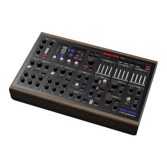
Page 11: Frontpanel Overview
MD900 Frontpanel Overview Figure 1. [Front panel] 1. Oscillators (Wavetable & Algorithm) 7. Envelope Generators 2. NOISE Oscillator (Sample based) 8. PART Selection 3. Mixer (OSC1 + OSC2 + Noise) 9. Quick navigation keys & Selection wheel 4. Wave-shaper 10. Touch display 5. -
Page 12: General Panel Functions
MD900 General panel functions Focus-keys Most sections have a focus button on the right side of the label bar. After pressing this focus button, the corresponding section is displayed on the touch display. On the left side of the label bar this selection is indicated by a red LED, see Figure 2. -
Page 13: Rear Connections
MD900 Rear connections Figure 4. [Connections] 1 Power supply connector, power switch & indicator light 2 USB 2.0 Host connectors 3 Pedal connectors • Sustain/Hold Pedal (optional functions see ENVELOPE GENERATORS) • Expression Pedal 4 DIN-MIDI Ports (IN, OUT, THRU) 5 Audio connectors •... -
Page 14: Commissioning
MIDI (DIN / USB). Default via MAIN-HEADP. setup after shipping, the MD900 uses MIDI Channel 1, 2, 3, 4 for The audio outputs are designed with a relatively Part A, B, C, D from the DIN MIDI IN jack. -
Page 15: Connections Details
Connections details program) and per envelope generator. (see ENVELOPE USB 2.0 Host-Interfaces GENERATORS) The MD900 has 3 x USB 2.0 host ports. These USB ports allow • Sustain: Selects between two different release the connection of MIDI "class-compliant" keyboards or times. -
Page 16: Midi In
MD900 MIDI IN This DIN MIDI input jack allows the connection of a MIDI keyboard or controller according to MIDI 1.0 specification. The control of the "Drum Sampler [see... -
Page 17: Midi Thru
MD900 DRUM (Sample-Player)] is possible via channel 10. The assignment of MIDI channels to parts is doable via the Info: If the AUDIO OUT-(L)R is used as stereo menu MIDI [see MIDI Settings]. output, nothing must be plugged into the jack socket OUT-L. -
Page 18: Touch-Display Overview
MD900 TOUCH-display overview The following Figure 5. [Touch-Display] shows the general controls. Continuous controller groups 1-4 allow setting parameters of a corresponding section (e.g. Oscillator 1). Each continuous controller group can have up to 5 levels. I.e. the corresponding parameter of the group can be selected on the touch display and then be changed by means of the endless controller. -
Page 19: Parameter-Label
MD900 The main menu tab is located in the upper display area. This Parameter-Label allows the menu selection to be made via the touch. The quick In the Figure 6. [Parameter Label] the parameter Label is shown selection keys allow an alternative, hierarchy-free quick in detail here NAME, VALUE and UNIT are displayed. -
Page 20: Synthesizer Structure
MD900 Synthesizer structure Figure 7. [Synthesizer Structure]... - Page 21 MD900 The Figure 7. [Synthesizer Structure] gives an overview of the internal structure of the MD900 and their interrelationships. The components are operated or set via the main menu and are explained in detail in the manual at the corresponding sections.
-
Page 22: Arranger
The selection list can be moved by the selection wheel or by the ARRANGER scroll bar up/down (dragging) and then selected (loaded) by The arranger in the MD900 allows you to save the entire setting. touching the row. These are:... -
Page 23: Save
SAVE TRACKING Save the arrangement with its current name. After power on of the MD900, this function is deactivated. Every movement of the controller is taken over immediately, which SAVE AS can lead to value jumps. If tracking is activated, changes are... -
Page 24: Drum (Sample-Player)
"drum sequencer" or externally via MIDI channel 10. Therefore, we call it only briefly DRUM. Info: The samples for DRUM/NOISE (wave files) can be loaded into the MD900 by the user. (see md900-backup-restore-en.pdf) Figure 9. [Drum KIT] GRID see DRUM-Pattern... -
Page 25: Instruments
MD900 INSTRUMENTS The independent drum instruments are one-shot sample players. To clarify the relationships, let's have a look on the file structure: For the Instruments see Figure 10 [DRUM-SAMPLE STRUCTURE]. This shows the relationship to the file structure. Each instrument has its access location to its samples which are offered for selection (Samples selection list). -
Page 26: Sidechain
MD900 Sidechain This parameter allows mixing these instruments to the sidechain Info: The DRUM sample player is quasi the 5th bus. This bus can be processed in the effect section. (e.g. PART and can play 14 samples simultaneously. It Dynamic Compressor) -
Page 27: Parts
MD900 PARTs The MD900 is equipped with 4 parts, so it can produce four different sounds simultaneously. The up to 16 stereo voices for these sounds are divided. The advantage is that the polyphony can be distributed to the sounds where it is needed. In other words, there are 4 synthesizers (we call them PARTs) which share a common voice pool. -
Page 28: Synth A (B, C, D)
MD900 If a category is now selected in the "List View", the presets are SYNTH A (B, C, D) listed and can now be selected and loaded in the same way. See Preset-Selection Figure 14. [Presets] This colored main menu tab represents the synthesizer of the corresponding PART. -
Page 29: Voice-Mode
MD900 SAVE PRESET AS Tune The touch-button SAVE_AS opens the keyboard and allows The TUNE parameter can be used to adjust the tuning of the saving under new names, see Figure 15. [Keypad]. corresponding SYNTH in cents [+/-100] to the normal tuning. -
Page 30: Master
MD900 PART MASTER Shows, with blue background, the part which is active in the This panel shows, with the two oscilloscopes, the signals Main menu and on the panel. [L]eft and Main [R]ight respectively, as they are passed on in sequence to the DAC (Digital Analog Converter). -
Page 31: Clip-Launcher
AKAI APCmini). Clips can be activated/deactivated via this The Clip Launcher, Menu Tab CLIP, is the central hub for controller. Navigation must still be done via the touch screen. performing live directly with the MD900. TRACK The panel (see Figure 16. [CLIP-Launcher]) is used for navigation,... -
Page 32: Open
TEMPO This label determines the beats per minute (BPM) and generates the MD900-wide internal beat. OPERATION By means of this label one of the following operations can be selected, the execution is triggered by pressing the endless controller. -
Page 33: Midi-Sequencer
The MIDI file selection list shows all files that have been loaded MIDI-Sequencer into the MD900 file system (see Data Import/Export manual). The MIDI sequencer is opened by activating the OPEN touch The length of the MIDI file is in quarter notes and is not button and selecting the corresponding clip in the launcher. -
Page 34: Midi Grid
MD900 MIDI Grid In this view the MIDI events are displayed with the note values. Info: The MIDI-Grid is a pure display and it can not With the help of the selection wheel the section can be enlarged be edited or reduced. -
Page 35: Arpeggiator
MD900 • SUBST: Determines which of the keys will be played as a ARPEGGIATOR substitute. The arpeggiator is opened by activating the OPEN touch button o none: No play and then selecting the corresponding clip in the launcher. The o last: The last key played... -
Page 36: Assign
MD900 • FACTOR: Sets the beat ratio between BPM beat and steps If not all keys are played, notes are played as substitutes according to the settings (Substitute). (steps)1 = All 4 Beats o 1/2 = All 2 Beats CHORD plays all played notes on this step. -
Page 37: Semitone
MD900 SEMITONE OCTAVE This menu tab allows you to transpose the note value upwards This menu tab allows transposition of the note value in octave in semitone steps. up/down. From C = 0 semitones (no transposition) to B = 11 semitones 0 = corresponds to the note value of the step without transposition. -
Page 38: Velocity
MD900 VELOCITY CVA (B, C) This menu tab sets the velocity value of the step with which the This menu tab allows to send a kind of virtual control voltage to note is struck. the corresponding synth engine. This allows step specific modulations. These virtual control voltages are found with the same name in the modulation matrix as a source and can be switched there. -
Page 39: Drum-Pattern
MD900 In the mode area, selecting the DRUM-Pattern corresponding instrument row The DRUM Pattern Editor is opened by activating the OPEN switches between input mode touch button and then selecting the corresponding clip (Track (highlighted in blue) and selection DRUMS) in the Launcher. The last opened pattern can always be mode. -
Page 40: Pattern-Duplication
MD900 The STEPS parameter defines the number of steps until repetition. If more than 16 steps are set, the selection wheel can be used to switch to the next page(s). Pattern-Duplication Once you have created a pattern page, it is easy to duplicate it. -
Page 41: Midi Settings
MD900 Pressing the UPDATE touch button updates the Devices list MIDI Settings (right). MIDI Devices If a connected USB MIDI keyboard is to be used, the USB device must first be linked (mapped) to a MIDI port (P1-P4). This allows MIDI Inputs the assignment to a part (A-D). - Page 42 MD900 The LABEL: PORT-CHN allows the selection of the port (e.g. P2). Pressing the encoder key switches between port & channel. This is indicated by ">" or "<". LABEL: START, END sets the active range where this part accepts note ON/OFF values (this is useful for splitting the keyboard)
-
Page 43: Voice Structure
MD900 Voice structure Figure 29. [Voice structure]... -
Page 44: Special Feature
The voice (synthesizer voice) in Figure 29. [Voice structure] with In principle, the MD900 has a total polyphony of 16 voices its sections (in the analog world modules) is responsible for the (synthesizer voices). If very complex sounds are loaded through sound generation in the MD900. -
Page 45: Unisono Detune
MD900 KBD-Mode Unisono detune: The KBD-MODE parameter allows to set the articulation With the parameter DETUNE a mutual detuning of the assigned behavior in the MONO voice mode voices in cent [+/-100] can be done (UNI2,3,4). The cent value is •... -
Page 46: Voice A (B, C, D)
MD900 VOICE A (B, C, D) This colored main menu tab represents the VOICE view and Info: On the panel it is possible to navigate directly serves as a clear navigation to the individual sections. By to this menu via the PARTs with the keys A, B, C, D. -
Page 47: Oscillator Wavetable Mode
MD900 OSCILLATOR Wavetable Mode There are 2 oscillators which are completely identical. We describe Oscillator 1 (short form OSC1) from PART A. The mode is switched with the SEL button on the panel. In this case we select the wavetable mode. -
Page 48: Wavetable Selection
Info: Wavetable files (.wav) can be loaded into the Info: If wavetables are loaded with less than 256 MD900 by the user. waves, these are expanded to 256 when loading the wavetable (linear interpolation) (see md900-backup-restore-en.pdf) -
Page 49: Fine
MD900 MORPH [P2] Depending on the MORPH algorithm set, the depth or the type UNISONO is changed. Unison mode expands the number (up to 4) of active oscillators (x2, x3, x4). At x1 and x5 this mode is inactive. -2x, -x3, -x4 is almost the same as described above, but with the... -
Page 50: Oscillator Algorithm Mode
MD900 COMMON PARAMETERS: OSCILLATOR Algorithm Mode The parameters PHASE, FINE, COARS, DETUNE, UNISONO, The "Algorithm" mode follows the typical virtual analog SPREAD and PAN are identical in both modes. See description approach, but with the possibility not only to generate the [OSCILLATOR Wavetable Mode] classic waveforms (SAW, PULSE, TRI etc.), but also to generate... -
Page 51: Panel
MD900 • Dual PWM Switching the oscillator mode is done by long pressing the SEL/MODE endless control. Symmetrical 2-fold pulse wave, changes the width from the center SHAPE (0-256). Long pressing of the UNISON key switches between • HSync SAW mute/unmute, i.e. -
Page 52: Noise
(+/- 0 to 100%). Basically, the wave sample files are located in the file system of the MD900. When a preset is saved, the sample content is also saved in the preset. Attention: The embedded sample in the PS: field... -
Page 53: Panel
If presets are exchanged between different MD900s and the confirmed beforehand by briefly pressing the Encoder, this selection will be loaded. preset contains a sample that is not found on the MD900's file system, this name is displayed in the PS: field. PANEL Info: Noise Sample Files (.wav) can be downloaded... -
Page 54: Mixer
MD900 MIXER With the two parameters SEL the signal path of the respective This section is the mixer for the two oscillators (OSC) as well as OSC can be defined. The SEL of the FLT-A path for the noise OSC. Furthermore, the signal routing is done additionally allows a crossfade XFADE between through which filter A, B path the signal is routed. -
Page 55: Filter A(B)
MD900 INPUT FILTER A(B) This parameter allows attenuating the input signal into the The filter section is explained here as a substitute for the FILTER FILTER. (0-100%) B. The LINK function is only available for FILTER A. Both the CUTOFF FILTER A and the FILTER B are designed in stereo. -
Page 56: Type
MD900 TYPE The filter type or filter model can be set with this parameter. The following filter types are available for selection: • LP24: Stereo Butterworth low pass Filter 24dB • MOOG LD12: Moog-style Transistor Ladder low pass 12dB • MOOG LD24: Moog-style Transistor Ladder low pass 24dB •... -
Page 57: Lfo 1(2,3)
MD900 LFO 1(2,3) DELAY The LFO Low Frequency Oscillator is an indispensable helper in This parameter allows to delay the LFO output signal (0.008s - the matter of modulation. The 3 x LFOs are explained on the 45s). basis of LFO 1. They are completely identical in operation. It... -
Page 58: Div
MD900 PANEL Sets beats (quarter note) per synchronous measure: LFO panel operation is done in the same way, only the DIV and NOTE parameters cannot be controlled from the panel. 1=4 QN, ½=2 QN, ¼=1 QN, 1/8=½ QN, 1/16=¼ QN, 1/32=1/8 QN The selection of the waveform is done with the encoder WAVE. -
Page 59: Envelope Generators
MD900 The curve view shows the progression over time, based on the ENVELOPE GENERATORS current settings. The release phase is shown from the dashed The four envelope generators (EG) are explained as red line. If a sound is played, the cursor shows where the EG is representative for all of them, since they are completely located in the curve. -
Page 60: Ratio A
MD900 SUSTAIN: RATIO A Selects between two release times. Release when the pedal is With this parameter you can change the attack curve from not pressed, Release B when the pedal is pressed. exponential to almost linear (0- 100%). HOLD:... - Page 61 MD900 PANEL FOCUS The panel operation allows changing the four most important Pressing the key also displays the EG in the main display. parameters (ATTACK, DECAY, SUSTAIN, RELEASE). Pressing the key again toggles between the two AMP_EG A/B. If the focus is placed on a completely different section, the The control range is divided into two exponential curves.
- Page 62 MD900 DEFAULT MODULATIONS – MATRIX This touch button creates the first four basic entries. The modulation matrix allows the connection of signal sources CLEAR with signal destinations. This is displayed in a list form. Deletes a selected entry. With the scrollbar this list can be searched and the desired entry can be selected and changed.
- Page 63 MD900 SIGNAL-ANIMATION 10 CVA Control Voltage A (Arpeggiator) 0 to 100% 11 CVB Control Voltage B (Arpeggiator) 0 to 100% The current target signal is displayed in the AMT column above 12 CVC Control Voltage C (Arpeggiator) 0 to 100% the Amount bar.
- Page 64 MD900 18 FLT-A.ENV Filter A Envelope +-100% 19 FLT-B.MD Filter B Modulation +-100% 20 FLT-B.ENV Filter B Envelope +-100% 21 AMP-A.ENV Amplifier A Envelope 0 - 100% 22 AMP-A.AM *Amplifier A Modulation 0 - 100% 23 AMP-B.ENV Amplifier B Envelope 0 - 100% 24 AMP-B.AM...
- Page 65 MD900 Figure 1. [Front panel] ............. 10 Figure 27. [DEVICES]..............40 Figure 2. [Example LFO Section] ..........11 Figure 28. [MIDI-PART Input] ........... 40 Figure 3. [Assistance-Display]........... 11 Figure 29. [Voice structure] ............42 Figure 4. [Connections] ............12 Figure 30. [VOICE Overview] ............ 45 Figure 5.
Need help?
Do you have a question about the MD900 and is the answer not in the manual?
Questions and answers