Table of Contents
Advertisement
Quick Links
OUTPUTS
NC
1
Electric
NO
Lock
Com
NC
2
Electric
NO
Strike
Com
NC
3
NO
Com
NC
4
NO
Com
NC
5
NO
Com
NC
6
NO
Com
NC
7
NO
Com
NC
8
NO
Com
-
C
COM PWR
+
CONTROL FUSE
JUMPERS
1.0 A MAX.
- PWR +
- CTL +
From
From
Lock
Relay
Power
Power
Supply
Supply
Figure 1 - LV-8RCL Wiring Diagram
OUTPUTS
1NC
LOCK
1NO
Com
4NC
4NO
Com
5NC
5NO
Com
8NC
8NO
Com
4x4
8D
-
+
PWR
Figure 2 - LV-8RCL Schematic Diagram
© Copyright 2022 - BASE Electronics, Inc.
Write Fuse Size Here
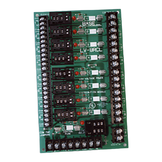
CONTROLS
1
BASE
2
w w w . b a s e e l e c t r o n i c s . c o m
3
LV-8RCL
4
4X4
5
LOW VOLTAGE POWER
6
DISTRIBUTION MODULE
7
8
DISC
RELAY
8 D
INPUT MAX.
30VAC/DC 8A 60Hz
ST
Com
NO
NC
CONTROLS
1
4
5
8
DISCONNECT
F
RELAY
CONTROL
FUSE
CP
-
+
ST
NC
DC
NO
CTL
Access Control
Panel Contact
1
2
Door Release
Pushbutton
3
4
Power Distribution Module
5
6
7
8
F
Normally Closed
Dry Contacts of
Fire Alarm Panel
2856-C Janitell Road • Colorado Springs, CO 80906 • (719) 540-9697 • Fax (719) 540-9698
LV-8RCL Specifications
• Indoor Temperature Range: -25° C. to +70°C.
• Electrical
Maximum Voltage AC/DC: 30V
Maximum Total Current: 8A
Maximum Recommended Current per Output: 2.5A
Maximum Total Relay Coil Current Draw: 1A
Connections: Captive Screw Terminals for #14 to #22AWG Wire
• Size: 5.00" wide by 8.00" long by 2.50 maximum height (inches) with relays installed.
• Mounting: (4) 3/8 inch high nylon standoffs included
• Indicators, Controls and Jumpers
Red LED Indicators at all 9 relay positions
Common Power - and +, Cut = Separate Relay Control Power, Uncut = Common Power
Mode Jumpers Uncut = 8 Continuous, Cut 8D = w/Disconnect, Cut 4x4 = 4x4 Mode
• Special Features
Mode Jumpers, 4x4 Mode
Power Disconnect Relay Socket with Auxiliary Contact Terminals
8 Output Isolation Relays with LED Indicators
2856-C Janitell Road • Colorado Springs, CO 80906 • (719) 540-9697 • Fax (719) 540-9698
The LV-8RCL Low Voltage Power Distribution Module is warranted by BASE Electronics against manu-
facturing defects in materials and workmanship for a period of 2 years from date of purchase. During this
period, any warranty repair required will be made at no charge for parts or labor. This warranty does not
apply to any work or materials provided by any outside persons or technicians involved in the installation,
unauthorized repair, connection, or testing of this product. This warranty does not cover any damage or
failure caused by or attributable to Acts of God, abuse, misuse, improper or abnormal usage, faulty or
improper installation or maintenance, neglect or accident. BASE Electronics is not responsible or liable for
any special, consequential or indirect damages resulting from or in connection with the use or performance
of this product as pertaining to economic loss, property loss, costs for removal or installation, or loss of
revenues or profit. Except as provided herein, BASE Electronics makes no expressed or implied warranties.
The duration of product performance for its intended purpose is limited to the duration set forth herein.
For Warranty or other repair, send the product postage prepaid to BASE Electronics and include Sender's
name, company, address, phone and brief problem description. BASE Electronics will notify sender of any
required repair costs not covered under this warranty prior to making such repairs.
This Warranty gives you specific legal rights. You may have other rights that vary from state to state.
BASE
LV-8RCL
Low Voltage
Installation and Operation Manual
BASE Electronics, Inc.
BASE Electronics, Inc.
Limited Warranty
Advertisement
Table of Contents

Related Manuals for BASE Electronics LV-8RCL


Summary of Contents for BASE Electronics LV-8RCL
- Page 1 Except as provided herein, BASE Electronics makes no expressed or implied warranties. The duration of product performance for its intended purpose is limited to the duration set forth herein. For Warranty or other repair, send the product postage prepaid to BASE Electronics and include Sender’s Figure 2 - LV-8RCL Schematic Diagram name, company, address, phone and brief problem description.
- Page 2 The information in this manual is believed to be accurate in all respects. However, BASE Electronics cannot assume When powering devices over considerable distances, the cabling resistance may be responsibility for any consequences resulting from the use thereof.
Need help?
Do you have a question about the LV-8RCL and is the answer not in the manual?
Questions and answers