
Summary of Contents for TPC SIMUTECH SIMVFD
- Page 1 SIMVFD USERS MANUAL VARIABLE FREQUENCY DRIVES www.simutechmultimedia.com support@simutechmultimedia.com...
-
Page 2: Table Of Contents
TABLE OF CONTENTS Operation Keypad................Function Keys.................. Status Display.................. Programming the SIMVFD..............Parameter Groups and Settings Navigation - 1......Parameter Groups and Settings Navigation - 2......SIMVFD Parameter Groups and Settings..........SIMVFD Parameter Summary............SIMVFD Parameter Details............Motor Parameters..............Ramp Parameters..............Volts/Hertz Parameters............ -
Page 3: Operation Keypad
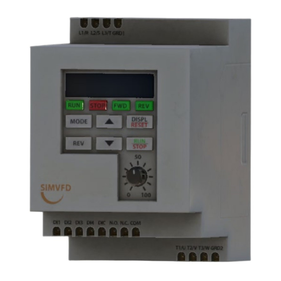
Operation Keypad The operation keypad includes an LED display, 4 LED indicators, 6 function keys, and a potentiometer. The diagram below shows all the features of the digital keypad and an overview of their functions. Function Keys The mode button is used to program the drive via various parameters, view parameters and store parameter settings. -
Page 4: Status Display
Status Display The Status Display shows the operation values and parameter settings of the SIMVFD. The display also has four LED Indicators that show the RUN, STOP, FWD, and REV status of the drive. Displaying the Drive Status Press the DISPL/RESET button on the keypad repeatedly to cycle through the status messages on the SIMVFD. The diagram below shows the order of the status messages and their definitions. -
Page 5: Programming The Simvfd
Programming the SIMVFD The SIMVFD parameters are divided into 4 groups to simplify navigation. These groups are further divided into sub-groups for the individual parameter settings within each main parameter group. When the MODE button is pressed, the drive enters Program mode where the user can then use the UP/DOWN keys to cycle through the available parameter groups. -
Page 6: Parameter Groups And Settings Navigation - 2
Parameter Groups and Settings Navigation - 2 NOTE: Pressing the DISPL/RESET button at any time backs out 1 mode level. If pressed while at the parameter level, user is backed out to the sub-group level. If in a sub group, user is backed out to the Main Group Level. -
Page 7: Simvfd Parameter Summary
SIMVFD Parameter Summary Parameter Summary – Motor Parameters (0-_) Parameter Description Range Default Setting User Setting Motor Nameplate Voltage 208, 230, 400, 460, 575 Motor Nameplate Amps 3.80, 5.12, 6.10, 13.40, 18.00, 3.80 21.00 Motor Base Frequency 50, 60 Motor Base RPM 800, 970, 1155, 1450, 1725, 2000 800 Motor Maximum RPM P. - Page 8 Parameter Summary – Digital Parameters (3-_) Parameter Description Range Default Setting User Setting Source of Operation 0: Operation determined by Command digital keypad 1: Operation determined by external control terminals, keypad STOP is enabled 2: Operation determined by external control terminals, keypad STOP is disabled Digital Inputs 1 &...
-
Page 9: Simvfd Parameter Details
SIMVFD Parameter Details Motor Parameters Motor Nameplate Voltage Range: 208, 230, 400, 460, 575 Default Setting: 208 This parameter determines the Maximum Output Voltage of the drive. The Maximum Output Voltage setting must be less than or equal to the rated voltage of the motor as indicated on the motor nameplate. -
Page 10: Ramp Parameters
Ramp Parameters Stop Method Range: 0: Coast to Stop, 1: Ramp to Stop Default Setting: 0 This parameter determines how the motor is stopped when the drive receives a Stop command. Coast: The drive stops output instantly upon command, and the motor free runs until it comes to a complete stop. Ramp: The drive decelerates the motor to zero speed according to the deceleration time set in parameter 1-2. -
Page 11: Volts/Hertz Parameters
This parameter is used when the motor driving a load needs to accelerate more smoothly. As the value of this parameter is increased from 1 through 5, the length of the S-curve is increased. The S-curve is disabled with a setting of 0, where acceleration is based only on the Acceleration Time parameter;... -
Page 12: Digital Parameters
Jog Frequency Range: 0 to 200 Hz Default Setting: 10 This parameter sets the Output Frequency of the drive in Jog mode and can be adjusted in steps of 10 Hz. If wired to digital input 3 or 4 and enabled in parameter 3-2 or 3-3, the drive output can momentarily run the motor, accelerating and decelerating as per parameters 1-1 and 1-2. - Page 13 3-2 & 3-3 Digital Inputs 3 and 4 (DI3 & DI4) Range: 0: Input Disable, 1: External Reverse, 2: External Jog, 3: External Reset, 4: Speed Hold, 5: Increase Speed, 6: Decrease Speed, 7: External Fault (N.C.), 8: External Fault (N.O.) Default Setting: DI3: 7, DI4: 4 Range Explanations 0: Input Disable: When not used, the digital input (DI3 or DI4) should be set to 0, disabling that input.
-
Page 14: Maintenance And Inspection
Maintenance and Inspection Modern AC drives are based on solid state electronics technology. Preventive maintenance is required to operate the SIMVFD in its optimal condition and to ensure a long life. It is recommended that a qualified technician perform a regular inspection of the SIMVFD. -
Page 15: Troubleshooting
Troubleshooting Fault Codes The SIMVFD has a comprehensive fault diagnostic system that includes several different alarms and fault messages. Once a fault is detected, the corresponding protective functions will be activated. The fault codes are then displayed on the digital keypad display. NOTE: Faults can be cleared by a reset from the keypad or input terminal. - Page 16 oL1 Internal electronic overload trip. 1. Check for possible motor overload. 2. Check electronic thermal overload setting. 3. Increase motor capacity. 4. Reduce the current level so that the drive output current does not exceed the value set by the Motor Rated Current 0-1. ocA Over-current during deceleration: 1.
-
Page 17: Simvfd Quick Start
SIMVFD Quick Start Use this basic guide for a new or replacement drive installation. The following example will help you quickly set up your SIMVFD for a constant torque application. Parameter setup: Set 0-0 - Motor Nameplate Voltage (per motor data plate). Set 0-1 - Motor Nameplate Amps (per motor data plate).
Need help?
Do you have a question about the SIMUTECH SIMVFD and is the answer not in the manual?
Questions and answers