Table of Contents
Advertisement
Quick Links
INSTRUCTION MANUAL FOR DUERKOPP ADLER-251 MACHINE
MINI-MOTOR
賀欣全球售服網 / H. S. Global Service Network
服務專線 / SERVICE HOTLINE : +886-2-2676-5203
傳真 / FAX : +886-2-2689-6600, 2689-3657
電子郵件 / E-MAIL : service@hohsing.com.tw
網址 / WEBSITE : http: // www.hohsing.com
HVP-20-4-25 FOR DA- 251
C-60
AC SERVO MOTOR
ENGLISH
中國地區 (CHINA)
服務專線 : +86-21-64897184
傳真 : +86-21-34074260
網址 : http: // www.hohsing.com
HSVP20U06 - 1
2008. 07
Advertisement
Table of Contents

Related Manuals for Dürkopp Adler HVP-20 Series

Summary of Contents for Dürkopp Adler HVP-20 Series
- Page 1 AC SERVO MOTOR INSTRUCTION MANUAL FOR DUERKOPP ADLER-251 MACHINE HVP-20-4-25 FOR DA- 251 MINI-MOTOR C-60 ENGLISH 賀欣全球售服網 / H. S. Global Service Network 中國地區 (CHINA) 服務專線 / SERVICE HOTLINE : +886-2-2676-5203 服務專線 : +86-21-64897184 傳真 / FAX : +886-2-2689-6600, 2689-3657 傳真...
-
Page 2: Table Of Contents
Model : HVP - 20 Series Contents 1. Safety Precaution Page (1). Work environment ……………………………………………………………………………………… (2). Safety in installation ……………………………………………………………………………………… (3). Safety in operating …………………………………………………………………………………… (4). Safety in maintenance and repairs ……………………………………………………………………… (5). Regulation in maintenance and repairs ………………………………………………………………… (6). Danger and caution signs ……………………………………………………………………………… (7). - Page 3 Page 7. How to Use Reset Function ……………………………………………………………… 8. Basic Troubleshooting (1). Error code and measurement …………………………………………………………………… (2). HVP-20 parts list ………………………………………………………………………………………… 9. HVP-20-4-25 Pin Assignment …………………………………………………………… Appendix : (1). Level 1 parameter list ………………………………………………………………………………… (2). Level 2 parameter list ………………………………………………………………………………… Bottom page : 7-Segment Display Characters Compare Chart...
-
Page 4: Safety Precaution
1. Safety Precaution When install and operate HVP-20 MINI Servo Motor, precaution must be taken as the following. This product is designed for the industrial sewing machines and must not be used for other purposes. (1). Work environment (a). Power voltage: Only use Power Voltage indicated on the name plate of the HVP-20 in ±10 % ranges. -
Page 5: Safety In Operating
(d). Grounding: 1. To avoid the static interference and current leakage, all grounding must be done. Power wire 1 Φ 220 V Ground Wire (Green/Yellow) must be grounding. Grounding Green/Yellow 2. Use the correct connector and extension wire when connecting ground wire to Earth and secure it tightly. -
Page 6: Installation And Adjustment (1).Control Box Installation
2. Installation and Adjustment (1).Control box installation : a). Install the motor and control box under the table b). Install the pedal with speed control unit c).Finished diagram V-belt Speed control unit Pitman rod Control box and motor (2).Operation box installation : a). -
Page 7: Speed Control Unit Forward / Backward Function & Force Adjustment
(4). Speed control unit Forward / Backward function & force adjustment : Delivery condition the inside torsion spring “E” is in position „1“. After the adjustment of the outside springs (chap.3) the inside torsion spring (E) can be adjusted additionally. a). -
Page 8: Installation Of The Synchronizer
(5). Installation of the synchronizer : (a). Install the synchronizer with the copper screws on the machine head. WARNING: The screws must be copper, if using iron, it will cause the needle positioning abnormal and also cause the 2 magnets in the hand wheel to be demagnetized. (6). -
Page 9: Needle Position Adjustment
(8). Needle position adjustment : (a). After installing the synchronizer, toe down the pedal and let the machine running few stitches, then check the needle position. (b). If motor stop at up position, the top white dot on hand wheel should be aligned with the index dot on the sewing machine. -
Page 10: Power Connection And Grounding (1). Single Phase And Three Phase Connection
3. Power Connection and Grounding (1). Single phase and three phase connection : Green/yellow wire is the ground wire. Single Phase ( AC220V) Brown Blue Green / Yellow ( grounding wire ) To control box Brown Three Phase ( AC380V) Black Blue To control box... -
Page 11: The Load Balance When Use 1Φ / 220 V Motor Used On 3 Φ / 220 V Power Source
(3). The load balance when using 1Φ / 220V motors in 3Φ / 220V power system : Please install the power connections as the following diagrams for the load balance. (4) How to change solenoid supply voltage : (DC: 24 V OR 30 V) When changing the solenoid voltage to 24V or 30V, use the JP1 and JP2 on the power board to do the jumper switch. -
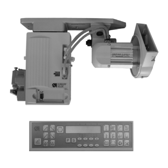
Page 12: Part Name Of The Control Box
4. Part Name of the Control Box (1). Use the following numbers cross reference with the control box picture : : Mounting bracket for under table motor. : Motor power socket : Standing operation panel socket : Motor encoder socket :... -
Page 13: Exterior Of The Control Box
(2). Exterior of the control box : Control box front side Control box right side Control box left side... -
Page 14: When Use With F-10 Mini Panel / Operation Box
5. Key Functions on Operation Panel / Box (1). When use with F – 10 mini panel / operation box : Function keys for the Function keys for the Function keys under parameter mode lock-stitch machine interlock stitch machine Enter the parameter area Enter the parameter area Also act as parameter increment key Needle up... -
Page 15: When Use With C-60 Operation Box
(2). When use with C-60 operation box : Function Operation of Sewing Machine Double start back tacking (A,B sections) Single start back tacking (A,B sections) Half start back tacking (B section ) Start / End back tacking selection Double end back tacking (C,D sections) Single end back tacking (C,D sections) Half end back tacking (C section) 1). - Page 16 As the treadle is toed down, all the seams of bar tacking, A、B、C、 D sections will be completed with E times, and the trimming cycle will be finished automatically Bar tacking Note:When the bar tack sewing start, it will not stop until the trimming cycle finished, except for the treadle heeling back to cancel the action.
- Page 17 1).When function is turned ON, slow start activated at first run of motor start. After trimming, it will activate again on next Slow start motor start. 2). Speed of the slow start can be set by parameter [007. S]. 3). Number of stitches can be set by parameter [008.SLS]. Needle stop setting Needle up / down LED ON= Stop at UP position...
-
Page 18: Parameter Adjustment (1). How To Enter【Normal Mode
6. Parameter Adjustment (1). How to enter【Normal Mode】: Just turn ON the power to enter【Normal Mode】 Display for interlock Machine / or Display for lockstitch when parameter 134 KLK =ON Machine C-60 : see note. (2). How to enter 【Parameter Mode】level: Parameter Mode Operation First display... -
Page 19: How To Set The【Parameter Value】With C-60 Operation Panel
(4). How to set the【Parameter Value】with C-60 operation box : d. Use the key under the Enter one of the key to select the 【 Parameter Mode A to B 】 A、B、C、D area to set the value. target parameter number. c. -
Page 20: How To Use Reset Function
7.How to Use Reset Function 1. Before【Reset】, please confirm the current machine code and any special setting for the parameter. Once reset and all the setting will return to the factory default. 2. After【Reset】, If the machine code is not match with the machine head. It could damage the machine head or cause machine not working properly. -
Page 21: Basic Troubleshooting
8. Basic Troubleshooting (1). Error Code and Measurement: Error Code Cause of The Problem Status and Measurement Motor will be shut down. 1. Power module detected error. ER0. 1 Please check the power module. 2. Abnormal over current or voltage occurred.. Please check the power board over current circuitry. - Page 22 Error Code Status and Measurement Cause of The Problem Motor still can run, but all output signals and operation box pattern sewing function will be invalid.. 1. Machine solenoid shorted. ER0. 9 Please check the machine solenoids; or the solenoid resistance value is 2 Ω less. 2.
-
Page 23: Hvp-20 Parts List
(2). HVP-20 Parts List : 1. Motor Parts : 2. Control Box Parts : 2-17 2-16 2-10 2-11 2-14 2-12 2-13 2-18 2-15 Order Code Parts Name Description Order Code Parts Name Description VP-50AB007-CE 2VP3432209AXL Motor with bracket 2VP20106003 Speed Control Unit 9800 370003 9800 170028 315BGV150... -
Page 24: Hvp-20-4-25 Pin Assignment
9. HVP-20-4-25 Pin Assignment ENCODER 2 UP DOWN FOOT SWITCH A PHASE +12V B PHASE External START variable resister KNEE SW. ENCODER FOOT SWITCH TRIMMER SAFETY SW. OPERATION BOX +12V +12V +12V +12V 2 INL SAFETY SW. T1out SAFETY SW. R1in U SW. - Page 25 PAGE - 1 HVP -20 Parameters List for DA-251 (MAC. 35) Parameters Parameters Function Range Pre.setting Description Code Maximum sewing speed 50 - 9999 spm 4000 Maximum speed adjustments The slow start operation mode is selected. This is valid when the panel [SL] key is ON in the normal mode. T:Slow start operation will begin when the power is turned ON or when the first toe down after thread trimming, SLM Slow start operation mode or the first external run signal (S0,S1) is turned ON.
- Page 26 PAGE - 2 HVP -20 Parameters List for DA-251 (MAC. 35) Parameters Parameters Function Range Pre.setting Description Code Additional 15 stitches are added to the Start and End back-tacking stitches function selection. 15 stitches plus on Start/End back-tacking ON/OFF ON:Valid. (with C60) OFF:Invalid.
- Page 27 PAGE - 3 HVP -20 Parameters List for DA-251 (MAC. 35) Parameters Parameters Function Range Pre.setting Description Code Wiper function selection. WON Wiper function selection ON/OFF ON:Enable. OFF:Disable. Trimmer function selection. Trimmer function selection ON/OFF ON:Enable. OFF:Disable. Counter function mode selection. NOP :...
- Page 28 PAGE - 4 HVP -20 Parameters List for DA-251 (MAC. 35) Parameters Parameters Function Range Pre.setting Description Code MAC Machine Code 0 - 101 Machine code switchover Positioning Mode selection. Positioning Mode selection ON/OFF ON:One position UP only. (ON=UP ONLY, OFF=UP/DOWN ) +...
- Page 29 PAGE - 5 HVP -20 Parameters List for DA-251 (MAC. 35) Parameters Parameters Function Range Pre.setting Description Code ON : No foot lifting at heeling pedal. Cancel foot lifting at full- heeling pedal ON/OFF OFF : Has foot lifting at heeling pedal. ON : No function at heeling pedal.
- Page 30 PAGE - 6 HVP -20 Parameters List for DA-251 (MAC. 35) Parameters Parameters Function Range Pre.setting Description Code Delayed timing prior to upper trimmer engaged 0 - 990 ms Only valid when 【078. TRM】set at『 KB 』mode. at down-stop Signal output from the wiper MW. Setting timing of upper trimming at down-stop 0 - 2500 ms See the KB timing chart.
- Page 31 PAGE - 7 HVP -20 Parameters List for DA-251 (MAC. 35) Parameters Parameters Function Range Pre.setting Description Code W : Regular wiper function (active 1 time when full heeling back after sewing) O : Wiper works at each full heeling back (unlimited ) 112 WMD Wiper function related to full-heeling pedal W/O/A...
- Page 32 7-Segment Display Characters Compare Chart : Arabic Numerals Actual Numbers Display Numbers English Alphabet Actual Alphabet Display Alphabet Actual Alphabet Display Alphabet Actual Alphabet Display Alphabet...
Need help?
Do you have a question about the HVP-20 Series and is the answer not in the manual?
Questions and answers