Advertisement
Quick Links
Advertisement

Subscribe to Our Youtube Channel
Summary of Contents for Sunways ST 1000
- Page 1 Energy Connects All Sunways Datalogger ST 1000 Installation Guide...
- Page 2 CONTENTS Product Introduction Installation Wiring RS485 Address Setting Configure Datalogger Communication Configuration...
-
Page 3: Product Introduction
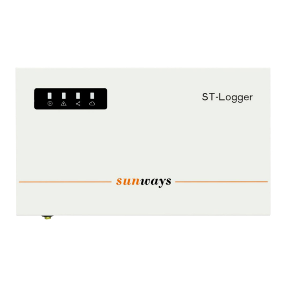
1. Product Introduction Indicator description Indicator Status Description Always on Normal operation No power Normal Alarm Always on Data logger has fault All PV inverters connected to the Always on datalogger are online Connection One or more PV inverters connected to the Flash datalogger are offline Always on... - Page 4 1. Product Introduction WIFI Antenna Meter connection port 12V DC Input Three RS485 Power Port communication ports Lan port (30 units can be connected to each port)
-
Page 5: Datalogger Wiring
2.1 Datalogger Wiring Port 1 Port 1 Connection in daisy chain AC 220/230V Cable Specification: two core, twisted pair, 2x1.5mm², shielding, pure copper RS485 signal wire. Meter Datalogger... -
Page 6: Inverter Wiring
2.2 Inverter Wiring Datalogger RS485 A Datalogger RS485 B Port 1 Port 2 Port STS 1-11KTL... - Page 7 2.3 Meter Wiring Cable Specification: Cable Specification: 1mm² pure twisted pair, 2x2.5mm², copper cable shielding, pure copper wire. Phase Meter & CT Direction Ia* -S1 P1: House (Load) Ia-S2 P2: Grid Meter Grid...
- Page 8 3.1 Inverter RS485 Address Setting Main Window Waiting Checking Normal Fault Info PV Voltage PV Current Grid Voltage Model General Grid Current E-Day E-Total H-Total Name Settings Grid Freq Modbus System Info Addr Short press(1s),switch window Setting Long press(3s),enter the lower Menu Set the address starting from 1, the recommended maximum value is set to 90.
- Page 9 3.2 Meter RS485 Address Checking Step 1 Total active Ua/Ub/Uc Ia/Ib/Ic Frequency Addr 003 power PASS 0000 0001 BUS1 Addr Step 2 Srue BUS1 Addr ① Follow step 1 to check if the RS485 address setting is correct. The correct address is 003. ②...
-
Page 10: Configure Datalogger
4 Configure Datalogger Step 1: connect the inverter to the datalogger through a ethernet cable. Router Sunways server Fixed IP 10.10.100.254... - Page 11 4 Configure Datalogger Step 2: Change computer network adapter settings. Open network & internet settings. Click ‘Ethernet’ in the network & internet list. Double click ethernet icon. Find IP settings and click ‘Edit’.
- Page 12 4 Configure Datalogger Choose ‘Manual’ on the Edit IP setting page and open IPv4 edit button. Finally, enter the information as shown.
- Page 13 4 Configure Datalogger 1. Open the browser, enter URL 10.10.100.254 2. Fill in the account ‘admin’ and the default password ‘admin12’.
- Page 14 4 Configure Datalogger All datalogger information is shown on overview page.
- Page 15 4 Configure Datalogger 1. Enable the Export limit and fill in the Export power value. If fill in the value 0 means zero export. 2. Select the total number of inverters connected to the datalogger 3. Set the CT ratio, if the nameplate on the CT marked 200/5A, the ratio is 40.
- Page 16 5 Configure Datalogger a) Search for the WIFI name “ WIFI-AP********”, which released by the datalogger and connect to the hotspot. b) Open the URL 10.10.100.254, and input username and password “admin”. c) Click “STA Setting”, then click “Scan”, you can find the router WIFI signal. (Note: Only support 2.412GHZ-2.484GHZ router) a) Finally, input the password in the blank and click “Save”.
Need help?
Do you have a question about the ST 1000 and is the answer not in the manual?
Questions and answers