
Summary of Contents for Olympus CFU03
- Page 1 CFU03/CFU05/CFU-PWZ Couplant Feed Unit User’s Manual DMTA048-01EN— Revision C February 2013...
- Page 2 Olympus NDT, 48 Woerd Avenue, Waltham, MA 02453, USA © 2009, 2013 by Olympus NDT, Inc. All rights reserved. No part of this publication may be reproduced, translated, or distributed without the express written permission of Olympus NDT, Inc. This document was prepared with particular attention to usage to ensure the accuracy of the information contained therein, and corresponds to the version of the product manufactured prior to the date appearing on the title page.
-
Page 3: Table Of Contents
DMTA048-01EN, Rev. C, February 2013 Table of Contents Labels and Symbols ................... 1 Important Information — Please Read Before Use ........5 Intended Use .......................... 5 Instruction Manual ........................ 5 Equipment Compatibility ..................... 6 Repair and Modification ....................... 6 Safety Symbols ........................6 Safety Signal Words ....................... - Page 4 Water Connections ....................29 2.3.1 Connecting the Water Supply Tube ............. 29 2.3.2 Connecting the Water Outlet Tube on CFU03 and CFU05 ....... 30 2.3.3 Connecting the Water Outlet Tube on CFU-PWZ ........32 Vacuum Suction System (CFU05) ................33 2.4.1...
-
Page 5: Labels And Symbols
Figure i-1 on page 1 (CFU-PWZ is shown, however the rating label for the CFU03 and CFU05 are at the same location). If any or all of the labels or symbols are missing or illegible, please contact Olympus. -
Page 6: Table 1 Content Of The Rating Labels
DMTA048-01EN, Rev. C, February 2013 Table 1 Content of the rating labels 2 Labels and Symbols... - Page 7 The CE marking is a declaration that this product conforms to all the applicable European Directives. See the Declaration of Conformity for details. The Declaration of Conformity is available through your local Olympus representative. Labels and Symbols 3...
- Page 8 DMTA048-01EN, Rev. C, February 2013 4 Labels and Symbols...
-
Page 9: Important Information - Please Read Before Use
Instruction Manual This instruction manual contains essential information on how to use this Olympus product safely and effectively. Before using this product, thoroughly review this instruction manual. Use the product as instructed. -
Page 10: Equipment Compatibility
DMTA048-01EN, Rev. C, February 2013 Equipment Compatibility The CFU03 and CFU05 Water Pumps are compatible with the Olympus scanners and wedges. The CFU-PWZ Water Pump is compatible with the Olympus PipeWIZARD. Using incompatible equipment could cause malfunction and/or equipment damage. -
Page 11: Safety Signal Words
DMTA048-01EN, Rev. C, February 2013 High voltage warning symbol This symbol is used to alert the user to potential electric shock hazards greater than 1000 volts. All safety messages that follow this symbol shall be obeyed to avoid possible harm. Safety Signal Words The following safety symbols might appear in the documentation of the equipment: The DANGER signal word indicates an imminently hazardous situation. -
Page 12: Note Signal Words
DMTA048-01EN, Rev. C, February 2013 Note Signal Words The following safety symbols could appear in the documentation of the equipment: The IMPORTANT signal word calls attention to a note that provides important information, or information essential to the completion of a task. The NOTE signal word calls attention to an operating procedure, practice, or the like, which requires special attention. - Page 13 To avoid the risk of electric shock, do not perform any work on the equipment unless qualified to do so. For any problem or question regarding this equipment, contact Olympus or an authorized Olympus representative.
-
Page 14: Equipment Disposal
Warranty Information Olympus guarantees your Olympus product to be free from defects in materials and workmanship for a specific period, and in accordance with conditions specified in the Olympus NDT Terms and Conditions available at http://www.olympus- ims.com/en/terms/. -
Page 15: Technical Support
Retain packing materials, waybills, and other shipping documentation needed in order to file a damage claim. After notifying the carrier, contact Olympus for assistance with the damage claim and equipment replacement, if necessary. - Page 16 DMTA048-01EN, Rev. C, February 2013 12 Important Information — Please Read Before Use...
-
Page 17: Introduction
Additional features apply to one or two of the specific pumps: • CFU03 and CFU05: These pumps have a valve to control the outlet flow. • CFU03 and CFU05: The water... - Page 18 DMTA048-01EN, Rev. C, February 2013 14 Introduction...
-
Page 19: Product Description
DMTA048-01EN, Rev. C, February 2013 1. Product Description Package Contents Package contents differ depending on the product: CFU03, CFU05, or CFU-PWZ (Table 2 on page 15). Table 2 Package contents Package Part Number Unit CFU03 CFU05 CFU-PWZ Component Quantity CFU03 Case ABIX0948 √... -
Page 20: Definition Of The Sides Of The Water Pump Case
For this manual, the sides of the water pump case are defined as shown on Figure 1-1 on page 17 and Figure 1-2 on page 17. This section displays the CFU-PWZ water pump, however the information is valid for the CFU03 and CFU05. 16 Chapter 1... -
Page 21: Figure 1-1 Top, Left, And Front Sides Of The Water Pump Case
DMTA048-01EN, Rev. C, February 2013 Front The side of the The side of the case where the case where the Olympus rating handle appears. This side will label appears. serve as a reference for identifying the back, right, and left sides, when... -
Page 22: Characteristics
The main characteristics of the water pumps are given in this section. For detailed specifications, see chapter 5 “Specifications” on page 53. 1.3.1 Right and Left Side Views The CFU03’s Right side view is shown in Figure 1-3 on page 18. Water from tank INLET... -
Page 23: Figure 1-5 Right Side Of Cfu05
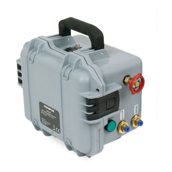
DMTA048-01EN, Rev. C, February 2013 The CFU05’s Right side view is shown in Figure 1-5 on page 19. Compressed connection to water tank or VACUUM OUTLET drain Water from tank INLET Power connection Figure 1-5 Right side of CFU05 The CFU05’s Left side view is shown in Figure 1-6 on page 19. Start/Stop button Flow control valve Water... -
Page 24: Figure 1-7 Right Side Of Cfu-Pwz
DMTA048-01EN, Rev. C, February 2013 The CFU-PWZ’s Right side view is shown in Figure 1-7 on page 20. Water from tank INLET Power connection Figure 1-7 Right side of CFU-PWZ The CFU-PWZ’s Left side view is shown in Figure 1-8 on page 20. Start/Stop button Water to PipeWIZARD... -
Page 25: Water Flow
Water Flow The diaphragm pumps have the following flow capacity: • CFU03 and CFU05: 3.78 L/min (1 GPM) • CFU-PWZ: 6 L/min (1.6 GPM) The units operate on both 120 VAC and 240 VAC. The pump inlet tube is equipped with a water suction filter, an in-line algae filter, and a check valve to ensure that the tube is always filled. - Page 26 DMTA048-01EN, Rev. C, February 2013 22 Chapter 1...
-
Page 27: Connections
DMTA048-01EN, Rev. C, February 2013 2. Connections In this section, all of the connections are described both in diagrams and procedures. Pay special attention to, and comply with the following instruction, in step 1 of many connection and disconnection procedures: “Ensure that the pump is turned off.” Not respecting this instruction could result in a bad power connection in the long term due to sparks. -
Page 28: Types Of Connections On The Water Pumps
DMTA048-01EN, Rev. C, February 2013 Types of Connections on the Water Pumps There are three common connections for the CFU03 and CFU05 Water Pumps. These are: • the power connection • the water from the water tank to the water pump INLET •... -
Page 29: Figure 2-2 Color-Coded Connections With Male Connectors On Pump
DMTA048-01EN, Rev. C, February 2013 CFU05: supply— Color code: plain CFU05: to tank or VACUUM OUTLET drain— Color code: red Water from tank— INLET Color code: blue Figure 2-2 Color-coded connections with male connectors on pump CFU05: Water Water OUTLET SUCTION wedges Figure 2-3 Plastic quick-coupling connections... -
Page 30: Power Connection
DMTA048-01EN, Rev. C, February 2013 CFU-PWZ: Water OUTLET PipeWIZARD Figure 2-4 Metallic connection with female connector on pump Power Connection The voltage requirement for the CFU Water Pumps is 100 VAC to 240 VAC. You must ensure that your power feed meets this requirement. The power cord supplied with the power supply varies, depending on your location. -
Page 31: Connecting The Cfu-Pwz Power Supply And The Remote Control
DMTA048-01EN, Rev. C, February 2013 CFU05 unit shown Power supply unit AC In connection Power supply Power cable DC IN receptacle LEMO connector Power plug Figure 2-5 Connecting the power supply to a pump To disconnect the power supply from the water pump Ensure that the pump is turned off. -
Page 32: Figure 2-6 Connecting The Remote Control To A Pump
DMTA048-01EN, Rev. C, February 2013 CFU-PWZ unit shown Start/Stop button, Power supply unit Remote control AC In connection, power cable CFU-PWZ: Remote control Remote DC IN LEMO control: receptacle connector DC IN Power supply LEMO Power plug receptacle connector Figure 2-6 Connecting the remote control to a pump Align the pins of the power supply LEMO connector with the holes of the remote control’s receptacle (Figure 2-6 on page 28). -
Page 33: Water Connections
Pump suction filter inlet Figure 2-7 Water supply tube To connect the water supply tube to the pump (CFU03, CFU05, and CFU-PWZ) Ensure that the pump is turned off. Select the tube with the blue color-coded metallic quick-coupling mechanism. -
Page 34: Connecting The Water Outlet Tube On Cfu03 And Cfu05
Figure 2-8 Water supply connection INLET To disconnect the water supply tube from the pump (CFU03, CFU05, and CFU-PWZ) Ensure that the pump is turned off. Pull back the blue ring of the coupling to release the tube’s male connector (Figure 2-8 on page 30). -
Page 35: Figure 2-9 Water Outlet Connection
OUTLET Figure 2-9 Water connection OUTLET To disconnect the water outlet (CFU03 and CFU05) Grab the tube with one hand. Push on the outer blue plastic ring of the connector to release the tube (see Figure 2-10 on page 31). -
Page 36: Connecting The Water Outlet Tube On Cfu-Pwz
DMTA048-01EN, Rev. C, February 2013 2.3.3 Connecting the Water Outlet Tube on CFU-PWZ The water outlet tube connects to the CFU-PWZ pump’s water connector. OUTLET To connect the water outlet tube (CFU-PWZ) Ensure that the pump is turned off. Select the water tube that has two male connectors with red color coding. Push one of the male connectors into the pump’s female water connection OUTLET... -
Page 37: Vacuum Suction System (Cfu05)
DMTA048-01EN, Rev. C, February 2013 Vacuum Suction System (CFU05) This section will document the three connections that are specific to the CFU05 pump. 2.4.1 Air Supply The water suction system on the CFU05 needs an adequate supply of compressed air to generate the required vacuum. -
Page 38: Water Discharge
DMTA048-01EN, Rev. C, February 2013 CFU05 unit Metallic quick-coupling mechanism Ring Figure 2-13 Compressed connection To disconnect the air-supply hose from the pump (CFU05) Pull back the ring of the coupling to release the hose’s male connector (see Figure 2-13 on page 34). Pull out the hose. -
Page 39: Water Suction Connection
The CFU05 uses suction to remove excess water from the wedges. The recovered water enters through the connection (see Figure 2-15 on page 36). SUCTION The water connection uses a plastic quick-coupling mechanism identical to SUCTION the one used by the CFU03/CFU05 water supply connection. OUTLET Connections 35... -
Page 40: Figure 2-15 Cfu05-Water Suction Connector
DMTA048-01EN, Rev. C, February 2013 CFU05: Water SUCTION Figure 2-15 CFU05—Water connector SUCTION To connect the water-suction tube Insert the water suction tube into the water connection (see Figure 2-16 SUCTION on page 36). Push the tube into the receptacle to trigger the plastic quick-coupling mechanism. CFU05 unit Water : Plastic quick coupling... -
Page 41: Figure 2-17 Cfu05-Disconnecting The Water Suction Tube
DMTA048-01EN, Rev. C, February 2013 To disconnect the water suction tube Grab the tube with one hand. Push on the outer blue plastic ring of the connector to release the tube (see Figure 2-17 on page 37). Pull out the tube. Outer blue plastic ring Figure 2-17 CFU05—Disconnecting the water suction tube Connections 37... - Page 42 DMTA048-01EN, Rev. C, February 2013 38 Chapter 2...
-
Page 43: Operation
This section presents the usual procedures to setup, operate during inspection, and shut down the CFU Water Pumps. Operating the CFU03 This section explains the operating procedure of the CFU03 water pump. To operate the CFU03 Ensure that all connections on the pump are correctly made. See chapter 2 “Connections”... -
Page 44: Operating The Cfu05
DMTA048-01EN, Rev. C, February 2013 Operating the CFU05 This section explains the operating procedure of the CFU05 water pump. To operate the CFU05 Ensure that all connections on the pump are correctly made. See chapter 2 “Connections” on page 23. Ensure that all connections on the scanner and wedges are correctly made. - Page 45 DMTA048-01EN, Rev. C, February 2013 Place the filter end of the pump’s inlet tube below the water level in the water tank. Start the pump using the appropriate start/stop button (pump or remote control), depending on the power connection. When you have finished your inspection and the unit is no longer required, turn off the pump using the appropriate start/stop button (pump or remote control), disconnect the power supply, and then remove the power plug from the AC power outlet.
- Page 46 DMTA048-01EN, Rev. C, February 2013 42 Chapter 3...
-
Page 47: Maintenance And Troubleshooting
DMTA048-01EN, Rev. C, February 2013 4. Maintenance and Troubleshooting This section presents procedures for maintaining, storing, and troubleshooting your unit. Maintaining the Water Inlet Tube’s Suction Filter The following procedure should be followed to ensure that the filter is clean and in good working condition. -
Page 48: Cleaning The Water Pump
To drain the water pump Remove the water inlet tube from the water tank. For CFU03 and CFU05 pumps only: Fully open the flow control valve. Start the pump using the appropriate start/stop button (on the pump or the remote control), depending on the power connection. -
Page 49: Spare Parts
21 °C, the waiting time is longer. Spare Parts Spare parts that can be ordered are documented in Table 3 on page 45. Table 3 Spare parts Spare Part Order Part Component CFU03 CFU05 CFU-PWZ Number Part Number CFU03... -
Page 50: Troubleshooting
2 “Connections” on page 23. Water leak or air leak Internal leak Contact your local Olympus NDT is present beneath the Service Center for repair. pump cover 46 Chapter 4... - Page 51 Table 4 Troubleshooting (continued) Problem Description Possible Cause Solution CFU05: Weak suction Internal leak (check Contact your local Olympus NDT or no suction for the presence of air Service Center for repair. leaks beneath the pump cover) Water leaks on...
- Page 52 DMTA048-01EN, Rev. C, February 2013 Table 4 Troubleshooting (continued) Problem Description Possible Cause Solution Motor not running Bad electric Check these connections: connection power plug in AC power outlet (wall) • power cable in the power supply unit’s AC In connection •...
- Page 53 Dirt on Remove dirt from the connector. INLET connector CFU03 or CFU05: Turn the pump valve counter Valve on the pump clockwise to allow more water partially or fully flow.
- Page 54 Damaged or Replace the water outlet tube. punctured water Contact your local Olympus NDT outlet tube Service Center for a replacement. Dirt on inlet filter Clean the inlet filter by following the procedure in section 4.1 “Maintaining the Water Inlet...
- Page 55 2.3.1 “Connecting the Water Supply Tube” on page 29. Damaged or Replace the water inlet tube. punctured water inlet Contact your local Olympus NDT tube Service Center for a replacement. The inlet tube has a Remove the kink.
- Page 56 DMTA048-01EN, Rev. C, February 2013 Table 4 Troubleshooting (continued) Problem Description Possible Cause Solution CFU-PWZ: Remote Bad electric Check these connections: control’s light is not connection Power plug in AC power outlet on when the remote (wall) control’s power • power cable in the power button is pressed supply unit’s AC In...
-
Page 57: Specifications
DMTA048-01EN, Rev. C, February 2013 5. Specifications This final section presents the technical characteristics of the CFU Water Pumps. CFU03 Specifications Table 5 on page 53 describes the specifications for the CFU03 water pump. Table 5 CFU03 specifications Item Specification CFU03 case Weight: 5.3 kg (11.68 lb) -
Page 58: Cfu05 Specifications
DMTA048-01EN, Rev. C, February 2013 Table 5 CFU03 specifications (continued) Item Specification Power supply adaptor 100 VAC to 240 VAC input to 24 VDC output, 3.5 A max. 24 V 150 W Power supply output LEMO connector Model: FFA Series: 2E, 4 Pins Part number: FFA.2E.304.CLAC60... - Page 59 DMTA048-01EN, Rev. C, February 2013 Table 6 CFU05 specifications (continued) Item Specification Inlet feed tube Weight: 0.8 kg (1.76 lb) Length: 3250 mm (127.95 in.) Outside diameter (OD): 16 mm (0.63 in.) Inside diameter (ID): 9 mm (0.35 in.) Filter (for inlet feed tube) Weight: 0.1 kg (0.22 lb) Length: 36 mm (1.42 in.) Outside diameter (OD): 58 mm (2.28 in.)
- Page 60 DMTA048-01EN, Rev. C, February 2013 Table 6 CFU05 specifications (continued) Item Specification Water resistance Designed for the IP54 rating. Pump: Outdoor use, wet locations Power supply: Indoor use (not water resistant) Altitude Up to 2000 m Humidity Maximum 80 % noncondensing Pollution tolerance Pollution level 2 Pump...
-
Page 61: Cfu-Pwz Specifications
DMTA048-01EN, Rev. C, February 2013 Vacuum Δp as a function of operating Suction capacity qn as a function of pressure p vacuum p Air consumption qn as a function of Suction capacity qn as a function of operating pressure p operating pressure p All provided data are subject to change. -
Page 62: Table 7 Cfu-Pwz Specifications
DMTA048-01EN, Rev. C, February 2013 Table 7 CFU-PWZ specifications Item Specification CFU-PWZ case Weight: 4.6 kg (10.14 lb) Overall dimension (L × W × H): 340 mm × 250 mm × 210 mm (13.39 in. × 9.84 in. × 8.27 in.) Inlet feed tube Weight: 0.8 kg (1.76 lb) Length: 3250 mm (127.95 in.) - Page 63 DMTA048-01EN, Rev. C, February 2013 Table 7 CFU-PWZ specifications (continued) Item Specification Remote control assembly Remote control output LEMO connector Model: FFA Series: 2E, 4 Pins Part number: FFA.2E.304.CLAC70 Overall dimension control box (L × W × H): 105 mm × 75 mm × 71 mm (4.13 in. × 2.95 in. × 2.90 in.) Weight: 1.3 kg (2.87 lb) Cord length: 10.7 m (35.11 ft) Control box connector: Power supply DC out...
- Page 64 DMTA048-01EN, Rev. C, February 2013 60 Chapter 5...
-
Page 65: List Of Figures
Top, left, and front sides of the water pump case ......... 17 Figure 1-2 Right, bottom, and back sides of the water pump case ........ 17 Figure 1-3 Right side of CFU03 ..................18 Figure 1-4 Left side of CFU03 ..................... 18 Figure 1-5 Right side of CFU05 .................. - Page 66 DMTA048-01EN, Rev. C, February 2013 62 List of Figures...
-
Page 67: List Of Tables
Content of the rating labels ..................2 Table 2 Package contents ....................15 Table 3 Spare parts ......................45 Table 4 Troubleshooting ..................... 46 Table 5 CFU03 specifications ..................... 53 Table 6 CFU05 specifications ..................... 54 Table 7 CFU-PWZ specifications ..................58 List of Tables 63... - Page 68 DMTA048-01EN, Rev. C, February 2013 64 List of Tables...
-
Page 69: Index
23 vacuum (CFU05) 33 safety footwear 9 water suction connection (CFU05) 35 CE marking 3 water supply tube 29 CFU03 contents, package 15 operation checklist 39 specifications 53 water flow capacity 21 damage, water in unused pump 44... - Page 70 10 procedures signal words 7 connecting air-supply hose 33 symbols 6 connecting CFU03 water outlet tube 30 setup procedures 39 connecting CFU05 water outlet tube 30 shut-down procedures 39 connecting CFU-PWZ water outlet tube 32 sides of the water pump case...
- Page 71 11 disconnection procedure (CFU05) 35 troubleshooting 46 water outlet connection type 24 water outlet tube connection procedure (CFU03, CFU05) 30 unfreezing the pump (maintenance) 44 connection procedure (CFU-PWZ) 32 disconnection procedure (CFU03, CFU05) 31 disconnection procedure (CFU-PWZ) 32...
- Page 72 DMTA048-01EN, Rev. C, February 2013 68 Index...
Need help?
Do you have a question about the CFU03 and is the answer not in the manual?
Questions and answers