Table of Contents
Advertisement
Quick Links
Annunciator
For the System 500, System 5000,
AFP-200, AM2020, AFP1010 and
Fire Alarm Control Panels
www.PDF-Zoo.com
The
ACM-8R
Control
Module
SFP-1024
firealarmresources.com
12 Clintonville Road
Northford, CT 06472
203-484-7161
FAX: 203-484-7118
Document # 15342
Document # 15342
Document # 15342
Document # 15342
Document # 15342
D1
07/24/97
07/24/97
07/24/97
07/24/97
07/24/97
Revision:
Revision:
Revision:
Revision:
Revision:
P/N 15342:D1
ECN 97-304
Advertisement
Table of Contents

Summary of Contents for Pittway Notifier ACM-8R
- Page 1 12 Clintonville Road Northford, CT 06472 203-484-7161 FAX: 203-484-7118 ACM-8R Annunciator Control Module For the System 500, System 5000, AFP-200, AM2020, AFP1010 and SFP-1024 Fire Alarm Control Panels Document # 15342 Document # 15342 Document # 15342 Document # 15342 Document # 15342 07/24/97 07/24/97...
- Page 2 www.PDF-Zoo.com firealarmresources.com...
-
Page 3: Table Of Contents
Table of Contents The ACM-8R Relay Module ..........4 Section One: Features of the ACM-8R ........4 Mounting ..............4 Section Two: Design Considerations ........... 5 Limits ..............5 Wire Runs .............. 5 Wiring Specifications ..........5 Receive Only Annunciators ........6 Receive/Transmit Annunciators ...... -
Page 4: Section One
Section One The ACM-8R Annunciator Control Module The ACM-8R is an element in the Notifier ACS class of annunciators. It provides the System 500, System 5000, AFP-200, AM2020, AFP1010 and SFP-1024 Fire Alarm Control Panels with a relay control module that can be mapped. The relays on this module can be selected for mapping anywhere in the System 5000 or System 500 memory map (by groups of eight). -
Page 5: Section Two
Section Two Design Considerations Limits The ACM-8R is a member of the Notifier ACS class of annunciators. Up to 32 annunciators may be installed on an EIA-485 circuit. The actual number of annunciator modules may be larger depending on the number of expander modules employed. Wire Runs Communication between the Control Panel and the ACM-8R is accomplished over a power-limited two-wire EIA-485 serial interface. -
Page 6: Receive Only Annunciators
Receive Only Annunciators For redundant annunciation of system points, annunciators can be configured as "Receive Only" annunciators. Receive Only annunciators must be set to the same address as the annunciators they duplicate, but are not fully supervisable. Receive Only annunciators intercept information being transmitted to a "Receive/Transmit" annuncia- tor so that this information can be duplicated at an intermediate display location. -
Page 7: Remote Power Source For Annunciators
Remote Power Source for Annunciators If the ACM-8R and other annunciator-type modules are to be powered from a remote supply (AM2020/AFP1010 only), a common connection between the negative battery terminals of each supply must be made. Fire Alarm Control Panel Annunciator in a Backbox, powered from Control Panel Power Loop... -
Page 8: Electrical Ratings
Electrical Ratings 24 VDC (must be power-limited). ACM-8R Current Draw from 24 VDC Input: Normal Standby: 0.030 amps Maximum current with all output relays activated: 158 mA. Relay Contacts UL contact ratings are 5 amps @ 125 VAC (resistive) or 30 VDC (resistive) and 2 amps @ 125 VAC (inductive). -
Page 9: Section Three: Installing The Acm-8R
Section Three: Installing the ACM-8R Remote Applications For remote applications, use the ABS-8R enclosure. Select an appropriate knockout on the ABS-8R enclosure. Mount the backbox. The enclosure must be connected to a solid Earth Ground (do not use conduit for this purpose). Pull all annunciator wiring into the enclosure. Wire the Terminal Blocks Connect annunciator power and EIA-485 wiring to the removable terminal blocks (refer to Figure 3-2). - Page 10 Figure 3-1: Mounting the Backbox Select a knockout on the backbox. Mount the backbox and draw all annunciator, power, and relay wiring into the enclosure. Connect the backbox to a solid Earth Ground. Do not use conduit for this purpose since it is not a reliable earth ground. On Terminating the Shield The EIA-485 circuit must be wired using a twisted- shielded pair cable having a Characteristic Imped-...
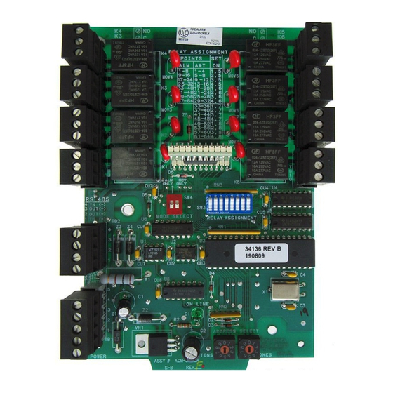
- Page 11 Figure 3-2: Configuring the ACM-8R SW3 Relay Assignment DIP Switches (refer to Table 3-1) ONLY ONLY MODE SELECT SW4-1: Set "ON" if relays are to be activated by alarms signals only. Set switch "OFF" for alarm and trouble activation. SW4-2: Set "ON" if the ACM-8R is to function in Receive Only mode on the EIA-485 circuit.
- Page 12 Multiple Annunciator Wiring • Do not "T-Tap" the power-limited EIA-485 circuit. It will not function properly. Wire as shown below. • Leave the 120 ohm resistor installed across the EIA-485 Out terminals at the last annunciator on the circuit (see below). Remove this resistor from all other annuncia- tors.
- Page 13 Relay Terminal Assignments The ACM-8R provides eight relays with Form-C contacts rated for 5 amps. The terminal assignments are illustrated below. For selecting where in the control panel's memory map these relays will be assigned, refer to Table 3-1. For information on wiring limitations, refer to the UL Power-limited Wiring Requirements section.
-
Page 14: Mapping The Acm-8R Relays
Mapping the ACM-8R relays The ACM-8R contains an 8 position DIP switch (SW3) that assigns annunciator points to the eight relays. Note that the address set on the Address Select switches affects exactly where the 8 relay group will fall in the control panel's memory map. Set these Annunciator Points Annunciator Points... -
Page 15: Row And Module Arrangement
Row and Module Arrangement When installing the ACM-8R for Alarm Only operation on a System 5000, the DIP switches on SW3 can be alternately understood as a row and module arrangement. Note: This correlation exists for each EIA-485 address. That is, the third cabinet row would become the 1st cabinet row at address 02. - Page 16 Relay Assignment Example - System 5000 Alarm Only Mode The ACM-8R can fol- Address 01 low the alarm status of any module in the Sys- tem 5000. To assign the ACM-8R to a mod- ule, two switches on SW3 must be set to "ON."...
- Page 17 Relay Assignment Example - System 5000 Alarm & Trouble Mode Address 01 The ACM-8R can fol- low the alarm and trouble status of any module half in the Sys- tem 5000. To assign the ACM-8R to a mod- ule half, two switches on SW3 must be set to "ON."...
-
Page 18: Relay Assignment Examples
Relay Assignment Example - System 500 Alarm Only Mode The ACM-8R can follow the alarm status of any module in the System 500. To assign the ACM-8R to a module, two switches on SW3 must be set to "ON." The two switches that must be set "ON"... - Page 19 EIA-485 Connection The EIA-485 circuit that drives the ACM-8R must be power-limited and connected as illustrated below. EIA-485 ( (+) EIA-485 to ACM-8R TB2-2 to ACM-8R TB2-3 CPU-500 EIA-485 ( (+) EIA-485 to ACM-8R TB2-2 to ACM-8R TB2-3 CPU-5000 EIA-485 Common Earth Ground (chassis) EIA-485 Loop 1 (+) EIA-485 Loop 1 (-)
-
Page 20: Mps-24A Main Power Supply
Figure 3-6: Supplying Power to the ACM-8R The ACM-8R requires 24 VDC regulated power to operate. This power may be obtained by the main power supplies illustrated on this and the next pages. MPS-24A Main Power Supply (AM2020, AFP1010 or System 5000 only): For the System 5000, connect the power run for the ACM-8R to MPS-24A TB3 Terminals 1 (+) and 2 (-) (1 amp max and power-limited). -
Page 21: Mps-24Bpca Main Power Supply
MPS-24BPCA Main Power Supply (System 500 Only) Connect the power run for the ACM-8R to MPS-24BPCA TB2 terminals 1 (+) and 2 (- ) (power-limited). No more than 200 mA current can be drawn from these terminals in standby or alarm. MPS-24BPCA ( - ) Common 24 VDC Power (+) -
Page 22: Appendix Aacm-8R And The System 5000
Appendix A ACM-8R and the System 5000 Capabilities When installed with a System 5000, the ACM-8R can follow the status of initiating and indicating circuits, relays, and several system control functions. Circuits: IZM-8 Initiating Device Circuits (alarm and trouble) ICM-4/ICE-4 Indicating Appliance Circuits (activation and trouble)* CRM-4/CRE-4 Control Relays (activation)* TCM-2 circuits (activation and trouble)* TCM-4 circuits (activation and trouble)*... - Page 23 AIM-200 Point Annunciation The CPU can be programmed for an alternate method of annunciating the AIM-200. Up to 192 intelligent devices can be annunciated on a single AIM-200 along the EIA-485 interface. The System 5000 annunciates the AIM-200 installed directly to the right of the CPU-5000. Note that an annunciator cannot be used to execute manual ON/ OFF control of intelligent AIM-200 points.
-
Page 24: Appendix Bacm-8R And The Am2020/Afp1010
Appendix B ACM-8R and the AM2020/AFP1010 Capabilities When installed with an AM2020/AFP1010 , the ACM-8R can follow the status of addressable devices, software zones, and several system control functions: Devices SDX-551 (Photo), CPX-551 (Ion) and FDX-551 (Heat) Intelligent Detectors. MMX-1, MMX-2, MMX-101 Monitor Modules, and CMX-1 and CMX-2 Control Modules. - Page 25 Multiple EIA-485 Circuits The SIB-2048 can support two EIA-485 circuits, each capable of spanning 6,000 feet @ 16 AWG, as illustrated below. ACM-8R ACM-8R EIA-485 Loop 1 EIA-485 Loop 1 (6,000 feet Max.) (6,000 feet Max.) ACS Power ACS Power To connect a second EIA-485 circuit, resistor R74 must be cut from the SIB-2048.
-
Page 26: Appendix Cacm-8R And The System 500
Appendix C ACM-8R and the System 500 Capabilities When installed with a System 500, the ACM-8R can follow the status of initiating and notification circuits, relays, and several system control functions. Circuits: IZ-4/IZ-4A/IZ-8 Initiating Device Circuits (alarm and trouble) IC-4/ICE-4/ICR-4L Notification Appliance Circuits (activation and trouble) CR-4/CRE-4/CR-4L Control Relays (activation) TC-2/TC-4 circuits (activation and trouble) -
Page 27: Appendix Dacm-8R And The Afp-200
Appendix D ACM-8R and the AFP-200 Capabilities The AFP-200 is capable of supporting two annunciator addresses, 01 and 02. All releases of AFP-200 software can support ACM-8R modules, no special software is required. The AFP-200 sends zone information to these annunciators, each of which have 64 points. - Page 28 Annunciator Address '01' AFP-200/ACM-8R Relay AFP-200 Zone ACM-8 Relay Settings Assignment System Alarm Relay 1 Alarm Only Mode Not used Relay 2 not used Not used Relay 3 not used ACM-8R Dip Switches Not used Relay 4 not used Not used Relay 5 not used 1=On 5=On...
- Page 29 AFP-200/ACM-8R Relay Annunciator Address '01' Assignment AFP-200 ACM-8R ACM-8R Alarm/Trouble Mode Zone Alarm Trouble Settings System Status 1. System Alarm 5. System Trouble ACM-8R System Status Relay 2 not used 6. Signal Silence Dip Switches System Status Relay 3 not used Relay 7 not used 1=On System Status...
-
Page 30: Appendix Eacm-8R And The Sfp-1024
Appendix E ACM-8R and the SFP-1024 Capabilities When installed with an SFP-1024 Fire Alarm Control Panel (FACP), the ACM-8R Relay Control Modules provide relay activation for each of the ten FACP zones plus special functions. Options exist to allow for alarm only or alarm and trouble activa- tions per zone. - Page 31 ACM-8R Alarm Activation Only DIP switch SW3 on the ACM-8R Relay Control Module is used to determine which FACP activations will trigger relays on the Relay Control Module. When installed with an SFP-1024 Fire Alarm Control Panel, use the following tables to set SW3 switches.
- Page 32 Table A-2: SW3 Settings for Alarm and Trouble Table A-2 provides the switch settings for ACM-8R DIP switch SW3 when configuring the relays to trigger for SFP-1024 alarm and trouble activation. Note that a maximum of five ACM-8Rs are required if relays are to be designated to trigger on any FACP status change.
- Page 33 Application Example #1: Zone Alarm Activation Only (no system status relays) Program the SFP-1024 at Level 3 addresses 02 - 03 for the proper address setting. The address selected must be the highest or maximum address value selected on any annunciator or ACM-8R connected to the EIA-485 port. (Refer to the Program- ming Instructions Section 3 of the SFP-1024 Installation Manual P/N: 50475).
- Page 34 Application Example #2: Zone Alarm and Trouble Activation (no system status relays) Program the SFP-1024 at Level 3 addresses 02 - 03 for the proper address setting. The address selected must be the highest or maximum address value selected on any annunciator or ACM-8R connected to the EIA-485 port.
- Page 35 Application Example #3: Two LED-10 Annunciators and 10 Alarm Only Relays (no system status) Program the SFP-1024 at Level 3 addresses 02 - 03 for the proper address setting. The address selected must be the highest or maximum address value selected on any annunciator or ACM-8R connected to the EIA-485 port.
- Page 36 Application Example #4: Two LED-10N Annunciators, 10 Alarm Only Relays and 20 Alarm and Trouble Relays (no system status relays) Program the SFP-1024 at Level 3 addresses 02 - 03 for the proper address setting. The address selected must be the highest or maximum address value selected on any annunciator or ACM-8R connected to the EIA-485 port.
- Page 37 LED-10N Address '01' FACP Program Level 3 Receive/Transmit Address 02 = '0' Address 03 = '4' LED-10N Address '02' Receive/Transmit ACM-8Rs set to Address '03' (Alarm Only) SW3-2 = ON SW3-3 = ON SW3-5 = ON SW3-5 = ON SW4-1 = ON SW4-1 = ON SW4-2 = ON SW4-2 = OFF...
- Page 38 Notes www.PDF-Zoo.com Document 15342 Rev D1 07/24/97 P/N 15342:D1 firealarmresources.com...
- Page 39 www.PDF-Zoo.com Document 15342 Rev D1 07/24/97 P/N 15342:D1 firealarmresources.com...
- Page 40 Limited Warranty ® NOTIFIER warrants its products to be free from defects in materials and workmanship for eighteen (18) months from the date of manufacture, under normal use and service. Products are date stamped at time of manufacture. The sole and ®...
Need help?
Do you have a question about the Notifier ACM-8R and is the answer not in the manual?
Questions and answers