Table of Contents
Advertisement
Quick Links
The ST365 Webpage Control application is included as a part of
each Spectrum Techniques ST365 hardware device. In order
to access this application it is necessary that the ST365 device
be LAN-connected to your network. With the device powered
on you may use a computer, smart phone, or tablet that is
connected to the same network to open a Chrome browser
window. From within this browser window you navigate to the
URL for the given ST365 device. Click the menu item labeled
"ST365 Webpage" to launch the control application.
Phone
(865)482-9937
E-mail
support@spectrumtechniques.com
User Manual
February 4, 2022
IMPORTANT NOTE
Spectrum Techniques, LLC
106 Union Valley Road
Oak Ridge, TN 37830
Fax
(865)483-0473
Web Site
spectrumtechniques.com
Advertisement
Table of Contents

Summary of Contents for Spectrum Techniques STU ST365
- Page 1 IMPORTANT NOTE The ST365 Webpage Control application is included as a part of each Spectrum Techniques ST365 hardware device. In order to access this application it is necessary that the ST365 device be LAN-connected to your network. With the device powered...
-
Page 2: Table Of Contents
The Wipe Test System ........................... 26 The Wipe Test ............................. 26 Checking the System Calibration ...................... 27 Taking a Background Reading ......................27 Measuring Wipes ..........................27 System Re-calibration ........................27 Warranty and Repair Information ..................... 28 Spectrum Techniques ST365 Webpage Rev. -
Page 3: Introduction
The purpose of this guide is to help you learn to use the ST365 Webpage application with your Spectrum Techniques hardware device. The ST365 webpage allows the user to copy data to your device’s clipboard and to use features described in the Using Your ST365 Device section found later in this document. - Page 4 The webpage you see is hosted by a web server located inside your ST365 device. The menu buttons displayed in green are used to access various features of the device. Click the menu button labeled ST365 Webpage. After a moment a new browser window appears that looks like this: Spectrum Techniques ST365 Webpage Rev.
-
Page 5: St365 Home Page
To prevent two users from having control of the same device at Spectrum Techniques ST365 Webpage Rev. -
Page 6: Using Your St365 Device
ST365 Home Page. The following discussion assumes that the user has used the control button to acquire control of their ST365 device and that the web server is now displaying its home page. Spectrum Techniques ST365 Webpage Rev. - Page 7 Immediately below the control button is a Display dropdown menu. See Figure 6. Figure 6 This menu allows the user to select from one of seven display options for the device. These options are: Counts Counts per Second Counts per Minute Spectrum Techniques ST365 Webpage Rev.
- Page 8 This menu allows the user to select from one of nine mode options for the device. These options are: Home Plateau Experiment Half-Life Experiment Set Preset Time Set Preset Runs Set Pause Time Set High Voltage Spectrum Techniques ST365 Webpage Rev.
- Page 9 This is the Display window for the page. See Figure 8 for the location of the Display window outlined in red. Figure 8 Immediately below the Display window is a row of three pushbuttons. See Figure 9. Spectrum Techniques ST365 Webpage Rev.
- Page 10 Click the Clear Counts button to reset the counts and the elapsed time to zero (0) as shown in the Display and Elapsed Time windows. Immediately below this row is a 3 x 2 grid of blue boxes. See Figure 13. Spectrum Techniques ST365 Webpage Rev.
-
Page 11: Assigning Parameter Values
The Counts Command is the simplest of the three commands. There are four parameters used by this command and that control how it operates. They are: Preset Time Preset Runs Pause Time High Voltage Spectrum Techniques ST365 Webpage Rev. - Page 12 If counts do not appear from the beginning, then this is likely because the voltage simply is not high enough for the probe to be able to generate counts. For the duration of the Spectrum Techniques ST365 Webpage Rev.
-
Page 13: Plateau Experiment Command
Plateau Experiment Setup Before setting up a plateau experiment make sure you have only one probe physically connected to a jack on the back of the ST365 device. Do not have both a GM tube and a Spectrum Techniques ST365 Webpage Rev. - Page 14 From here you may either type in the values you want to use or you may click the up or down arrow buttons to increment or decrement the parameter settings until each matches the value that you want. This example shows a typical plateau experiment setup where the start voltage Spectrum Techniques ST365 Webpage Rev.
-
Page 15: Plateau Experiment
The data graph will update to show the number of counts associated with each run. The data table will update to show the run number, counts, elapsed time, and voltage associated with each run. See Data Table section later on in Spectrum Techniques ST365 Webpage Rev. - Page 16 The plateau experiment command remains active until runs over the full voltage range have executed and counting has completed. Figure 18 shows a typical result after completion of a plateau experiment. Spectrum Techniques ST365 Webpage Rev.
- Page 17 Note that the data graph has a region located roughly between 860 and 880 volts where the measured counts from one run to the next remains fairly constant. This result from the plateau experiment indicates that the optimum voltage setting for the given isotope is around 870 volts. Spectrum Techniques ST365 Webpage Rev.
-
Page 18: Half-Life Experiment Command
The Half-Life Experiment Command is useful for verifying the half-life of an isotope with a relatively short half-life. An ideal isotope to use with this experiment is a Spectrum Techniques Cs-137/Ba-137m isotope Generator set (Item ID: ISO). This isotope generator allows the user to ‘milk’... -
Page 19: Half-Life Experiment
Click the Set button a second time in order to assure that the device has accepted the new parameter values. Half-Life Experiment Once you are satisfied with the parameter settings, click the Back button. Doing this takes you to a page that looks like Figure 20. Spectrum Techniques ST365 Webpage Rev. - Page 20 The half-life experiment command remains active until it has counted for the specified number of runs. Figure 22 shows a typical result after completion of a half-life experiment. Spectrum Techniques ST365 Webpage Rev.
-
Page 21: Data Table
See the Spectrum Techniques Lab Manual for an in-depth discussion of how to compute this constant for a given set of data. You may download this lab manual by visiting the Spectrum Techniques public website at https://www.spectrumtechniques.com/wp-content/uploads/2016/12/Spectrum-Techniques-... -
Page 22: Data Graph
Click the Mode dropdown menu and select the option Data Graph. Doing this takes you to a page that allows you to view the graphical data contained in the data graph. See Figure 24 for an example. Spectrum Techniques ST365 Webpage Rev. -
Page 23: System Operation
Techniques hardware device will result in erroneous data. Only connect one or the other, not both. 1. Connect the Spectrum Techniques hardware device to its AC adapter. 2. Connect a GM tube to the GM connector via a BNC cable. -
Page 24: Gm Tubes
1. Place the radioactive source in a fixed position close to the window or in the well of the detector. 2. Put the Spectrum Techniques device into Count mode and slowly increase the high voltage until the device begins to register count activity. Stop counts. -
Page 25: Resolving Time
If the resolving time of the detector is known, the true counting rate may be calculated from the measured rate using the following expression: n= m / (1 - mt) where n is the true counting rate, m the measured rate, and t the detector resolving time. Spectrum Techniques ST365 Webpage Rev. -
Page 26: The Wipe Test System
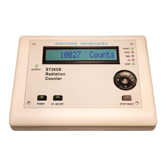
Solve for the resolving time using this equation T = (R(a)+R(b)-R(a+b)) / (2R(a) *R(b)) The resolving time of the Spectrum Techniques RADIATION COUNTER is very short and is not a significant factor compared to that of the GM tube. The Wipe Test System The Spectrum Techniques Radiation Counter will also operate with scintillation tubes for detecting low-level gamma and X-ray emission from a variety of samples. -
Page 27: Checking The System Calibration
Using the Cs-137 source supplied with the system, refer to the section Creating a Plateau Chart to obtain the correct operating voltage. See Figure 41 for an illustration of a typical detector plateau showing the optimum operating voltage. Spectrum Techniques ST365 Webpage Rev. -
Page 28: Warranty And Repair Information
The warranty does not cover damage caused by mishandling or misuse. GM tubes with broken windows are specifically excluded from this warranty. Accessory items not manufactured by Spectrum Techniques but supplied as part of our systems will be subject to the original manufacturer’s warranty.
Need help?
Do you have a question about the STU ST365 and is the answer not in the manual?
Questions and answers