Advertisement
Advertisement
Table of Contents

Related Manuals for Yaesu FR-50B


Summary of Contents for Yaesu FR-50B
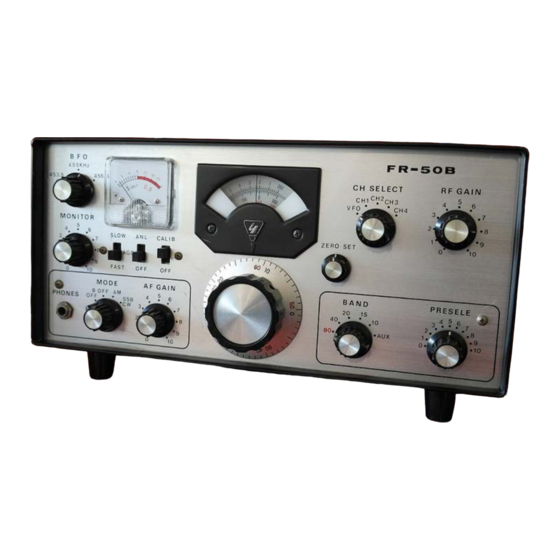
- Page 1 INSTRUCTION MANUAL FR-50B Page 1 of 22...
- Page 2 Notes: Changed kc/s and mc/s to kHz and MHz respectively Changed sized and weights to metric Any errors I found have been corrected. I have resisted making wholesale changes to the language used in the original instruction, where I have added comments these are in {italics}.
-
Page 3: Specifications
****************************** FR-50B COMMUNICATION RECEIVER ******************************* The model FR-50B Communication Receiver, designed for the amateur bands, provides high degree of sensitivity, selectivity stability. Basically, double conversion super-heterodyne receiver employing a variable oscillator for the first mixer stage, and a crystal controlled oscillator for... -
Page 4: Circuit Description
6BM8 Figure 1. Receiver Block diagram {V8 changed from 6AW6 to 6BM8} CIRCUIT DESCRIPTION Amplifier The high Gm tube V1 (6BZ6) provides a minimum of cross modulation. semi-remote cutoff pentode excellent characteristic. A 5 MHz trap is inserted to reject a spurious signal which could enter directly into the first I.F. - Page 5 C72 are temperature compensating capacitors which insure stability even in the 28 MHz band. Using the same dial mechanism as the FR- lOOB, with the 50 kHz variation per revolution of the knob, it is very effective for SSB and CW tuning. Buffer amplifier Tr2, silicon transistor type 2SC372, is employed in an emitter follower circuit.
- Page 6 (FR-50) and instead a slow/fast AGC switch took the place of the AGC on/off switch on the FR-50B model} 11. Mute & Monitor Circuit Adoption of a muting circuit enables smooth switching of transmit and receive.
- Page 7 OPERATION OF RECEIVER The following operating conditions should be observed. Antenna The antenna input impedance of the FR-5OB is 50 - 70 ohms. Use a matching antenna with coaxial lead-in. The receiving sensitivity is directly dependent on the quality of the antenna. However, a length of wire will suffice for casual listening.
- Page 8 If receiver is used while disconnected from the transmitter, M & G terminals must be shorted together. Figure 2. Connection of FL-50B transmitter and FR-50B receiver for transceive operation. 5. Transceive Operation Set the Xtal switch of the FL-50B in EXT OSC position. Switch to SPOT on the transmitter and set the carrier control to maximum, then adjust BFO PITCH for zero beat.
-
Page 9: Alignment Procedure
In the case of adjusting while communicating, turn the BFO PITCH to give the same tone from the received signal and monitored signal. Note that the BFO PITCH control can be used to provide a degree of "off-set" tuning in the transceive mode. ALIGNMENT PROCEDURE 1. - Page 10 6. Alignment of VFO Scale For correct alignment a 100 kHz marker is necessary, and if this is built-in it should be used. Adjust coils at the low frequency end, and trimmer condensers at the high end of each band for zero beat. Repeat this adjustment for greatest accuracy.
-
Page 11: Pin Number
VOLTAGE MEASUREMENTS (Volts d.c.) PIN NUMBER TUBE ♯ AC 6.3 ѻ ♯ ѻ ♯ ♯ -3.0 AC 6.3 AC 6.3 -0.4 ♯ AC 6.3 ♯ AC 6.3 ♯ AC 6.3 ♯ ∆ ∆ ∆ ∆ -0.7 AC 6.3 ∆ ∆ ∆... -
Page 12: Maintenance
MAINTENANCE This receiver has been thoroughly adjusted with the aid of much measuring equipment by the manufacturer, so re-adjustment should not normally be necessary a long time. If, due to component change or development of some fault, re-adjustment or repair should be found necessary, then this... - Page 13 sub-divisions main dial points. graduations tuning knob skirt closely represent divisions. The upper scale on the main dial is used for 10 meters this case knob skirt graduations represent divisions. The knob skirt may be adjusted independently of the knob itself by firmly holding the knob while turning the skirt, and can be set at 0 for 100 kHz points with a crystal calibrator.
-
Page 14: Part Locations
PART LOCATIONS Page 14 of 22... - Page 15 Page 15 of 22...
-
Page 16: Circuit Diagrams
CIRCUIT DIAGRAMS Page 16 of 22... - Page 17 Page 17 of 22...
- Page 18 Page 18 of 22...
- Page 19 Page 19 of 22...
- Page 20 Page 20 of 22...
- Page 21 This page is set to print landscape A3 Page 21 of 22...
- Page 22 This page is set to print landscape on a piece of paper 54cm wide by 25cm high Page 22 of 22...
Need help?
Do you have a question about the FR-50B and is the answer not in the manual?
Questions and answers