
Subscribe to Our Youtube Channel
Summary of Contents for Atlas Copco Unity
- Page 1 Unity Die Check Camera Issue 7 Original instructions for operation and maintenance of die check camera. Patents granted and pending.
- Page 2 Copyright © 2022 Atlas Copco IAS Intellectual property of Atlas Copco Industrial Assembly Solutions part of Atlas Copco Group. All rights reserved. No part of this publication may be reproduced, distributed, or transmitted without the express written permission of the publisher, except in the...
-
Page 3: Table Of Contents
Unity Die Check Camera, Issue 7 Contents Equipment ..........5 Introduction . - Page 4 Unity Die Check Camera, Issue 7 Contents Maintenance ..........30 7.
-
Page 5: Equipment
„ Patents granted and pending. Whilst every effort is made to ensure all information is correct, Atlas Copco IAS cannot be held liable for misprints or inaccuracies. Atlas Copco IAS also reserves the right to change the specifications of any product to improve its function without prior notice. -
Page 6: Introduction
2. 2 Intended Use of the Equipment Atlas Copco IAS warrants the supplied equipment to be correct and fit for purpose as described, declared and agreed in the quotation/sales order or supervening contract. Atlas Copco IAS accepts no liability for damages arising in whole or in part from: Non-observance of the supplied instructions. -
Page 7: Intended Use Of This Manual
2. 3 Intended Use of this Manual This manual is intended to be used by trained operators of the equipment and Atlas Copco IAS personnel when operating or maintaining the Self Pierce Riveting (SPR) equipment described. The information contained within this manual is provided as a guide for the intended use of the Henrob Self Pierce Riveting (SPR) equipment only. -
Page 8: Safety
Unity Die Check Camera, Issue 7 Safety It is important that the following safety precautions are observed: Only trained and authorised operators shall use this equipment. Contact Atlas „ Copco IAS or an approved engineer for help if you are in any doubt of your ability to operate or maintain the equipment. -
Page 9: Overview
Unity Die Check Camera, Issue 7 Overview An automated vision system for non-contact detection of broken Henrob self pierce riveting dies. The system is intended to detect gross die failures where a significant section of the die has broken away from the main body. It is not capable of detecting subtle variations in die condition such as low level contamination or surface defects. - Page 10 Unity Die Check Camera, Issue 7 Floor Stand for mounting camera when used with Robotic tool. Part number : 4222 624 861 HMI & Bracket (Basic) to be used for communication with camera. Part number : E4523 Bracket for mounting HMI to metal surfaces.
-
Page 11: Die Check Camera
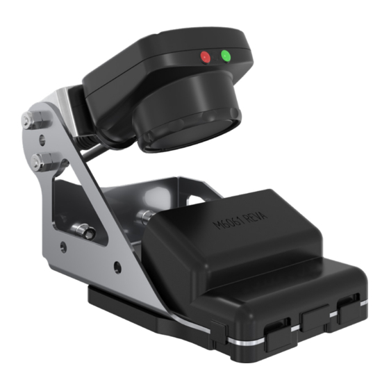
Unity Die Check Camera, Issue 7 4. 1 Die Check Camera 1 - Power I/O connector 2 - Ethernet connector 3 - USB connector 4 - Remote display connector 4. 2 Basic Operation The Die Check Camera is used to monitor the condition and integrity of the upsetting die currently installed onto the tool. -
Page 12: Installation And Set-Up
Unity Die Check Camera, Issue 7 Installation and Set-up 5. 1 Packaging & Storage Henrob riveting equipment is packed suitable for short term storage. In storage it should be protected from dust, moisture & excessive temperature (i.e. store at +5°C to +40°C, non- condensing). -
Page 13: Positioning
Unity Die Check Camera, Issue 7 5. 4 Positioning The Camera can be mounted either to a static location (such as to a magazine filling plate stand) or robot mounted. 5. 4. 1 Robot Mounted Tools For robot mounted tools the camera will be mounted to the die detection stand and positioned in one of two ways;... - Page 14 Unity Die Check Camera, Issue 7 NOSE-DIE GAP > 92mm: IN-LINE INSPECTION Nose Camera mounted to Camera mounted to Nose bracket type 1 - this bracket - this rivet enables attachment to enables attachment setter rivet fixed structure or robot...
- Page 15 Unity Die Check Camera, Issue 7 NOTE The 5° and 5mm adjustments are made to the robot and NOT the camera or bracket. Light source Centre line Die post & setter Centre line Move the gun over 5mm then rotate 5°...
-
Page 16: Powering On Die Check Camera
Unity Die Check Camera, Issue 7 5. 5 Powering on Die Check Camera The first time the camera powers up, it starts in Demo Mode. Demo Mode uses stored images and inspection parameters that demonstrate how the camera is set up without having to configure focus and lighting etc. - Page 17 Unity Die Check Camera, Issue 7 5. 6. 1 Die Alignment Check the die position relative to the Camera. Centralise the die to the camera Focusing Window and position the die at a distance of ~38mm from the camera. NOTE For the camera to be perpendicular to the die a minimum Nose-to-Die gap of 107mm is required.
- Page 18 Unity Die Check Camera, Issue 7 5. 6. 4 Auto-Exposure Main Menu > Imager > Auto Exposure Auto-exposure optimises the exposure time and gain for the current lighting conditions. Select the Main Menu button. Select the Imager button. Select the Auto Exposure button.
-
Page 19: Die Check Camera Teaching
Unity Die Check Camera, Issue 7 A Missed Trigger condition occurs when a trigger is received while sensor is busy „ inspecting the pervious image. This output signal will be set to active state. This signal will be reset upon resetting the ‘History’ on the statistics page. - Page 20 Unity Die Check Camera, Issue 7 Step 2: Select ROI Type. The Region of Interest (ROI) is the user-defined area on the screen that the sensor will analyse. The ROI Type can be rectangular, elliptical, or circular. ROI can be as large as the entire Field of View (FOV).
-
Page 21: Communications Setup
Unity Die Check Camera, Issue 7 5. 8 Communications Setup Step 1: From the camera display, select Main Menu icon as shown. Step 2: Select System icon. Step 3: Select Communications. Step 4: Select Ethernet I/O. Step 5: Set the IP address for the die detection image to ‘169.254.50.140’... -
Page 22: Inspection Setup
Unity Die Check Camera, Issue 7 NOTE If any further set up changes are required to be carried out at a later date the trigger must be changed back to internal and the Die put back into the Die check position. So that the HMI displays a live image. -
Page 23: Operation
Unity Die Check Camera, Issue 7 Operation 6. 1 Menu Layout The Main Menu has four sections: Inspection - to modify inspection settings „ System - to select the sensor Type and to manage the device „ Imager - to run the Auto Exposure routine and to make adjustments to functions „... - Page 24 Unity Die Check Camera, Issue 7 6. 1. 2 System menu map 6. 1. 3 Imager menu map Page 24...
-
Page 25: Menu Icons
Unity Die Check Camera, Issue 7 6. 1. 4 Logs menu map 6. 2 Menu Icons ICON ACTION ICONS The Main Menu icon is displayed on the bottom-left corner of the sensor display on the Home screen. It provides access to sub-menus that are used to set up the sensor. - Page 26 Unity Die Check Camera, Issue 7 ICON ACTION ICONS The Show Log Timestamps icon is one of the icons displayed in the upper-left corner of the Logs screen. Click this icon to show the time stamp for the Logs. The Go Back icon is located on the lower-left of the screen while working in the Main Menu.
- Page 27 Unity Die Check Camera, Issue 7 ICON ACTION ICONS The Elliptical Mask icon displays on the left side of the screen when a mask is selected. Press to cycle through and select a Circular, Elliptical, or Rectangular- shaped mask. The Rectangular Mask icon displays on the left side of the screen when a mask is selected.
-
Page 28: Inspections
Unity Die Check Camera, Issue 7 ICON COMMUNICATIONS LOG ICONS Port opened. Port closed. Indicates that the command has been processed without errors. Indicates that the incoming entry is stalled (no new bytes), or end-of-frame delimiter was not received, or client is not reading data on ethernet. - Page 29 Unity Die Check Camera, Issue 7 6. 3. 2 Inspection ID Main Menu > Inspection > Properties > Inspection ID Click on the drop-down arrow to view a list of IDs assigned to all inspections on this device. Choose any unused ID to change the ID of this inspection. The original ID will be marked as ‘Unused’.
- Page 30 Unity Die Check Camera, Issue 7 Maintenance There is no special maintenance required for the Die Check camera. 7. 1 Cleaning Depending on the environment, it may be necessary to clean the lens of the camera. WARNING Cleaning the camera requires entering the robot cell or working area.
- Page 31 Unity Die Check Camera, Issue 7 Technical Data 8. 1 Performance / Specification Die Check Camera USB 2.0 host connection 4-pin Pico (M8) female connector HMI connection 8-pin Euro-style (M12) female connector Ethernet connection 4-pin Pico (M8) male connector Camera (Imager) 1/3”...
- Page 32 Atlas Copco IAS Industrial Assembly Solutions Henrob Self-Pierce Riveting atlascopco.com...
Need help?
Do you have a question about the Unity and is the answer not in the manual?
Questions and answers