Advertisement
Advertisement

Summary of Contents for COVENANT HAVEN SC-100
- Page 1 Installation Manual SC-100 SC-200 SC-300/350 SC-600...
-
Page 2: Table Of Contents
TABLE OF CONTENTS DESCRIPTION PAGE NUMBER 1. Attention and Notes......1 & 2 2. Model #SC-100........3. Model #SC-100H........ 4 & 5 4. Model #SC-100L........ 5. Model #SC-200, #SC-300....7, 8, 9 & 10 6. Model #SC-300HG......7. Model #SC-350........12 &... - Page 3 ATTENTION: ®, do not spin or twist the gooseneck When operating the Safety-Comm. microphone. The gooseneck may be moved from side-to-side or up-and-down. However, twisting the gooseneck 360 degrees or more may damage the cabling within the microphone assembly. This type of damage to the Safety-Comm.® is not covered under the standard warranty.
- Page 4 Made in America Since 1993 Cleaning Procedures for Haven Window Intercoms Haven Technology has reviewed our intercom products and has the following recommendations to ensure cleanliness and reduce the potential for germ transfer. Window intercoms may be cleaned with commercially available household disinfectant wipes. If you use a spray disinfectant, do not spray directly on any part of the intercom.
- Page 5 Attention Users: Training/Operation tips Thank you for purchasing our Safety-Comm.® line of Box Office/Transaction Intercom Systems. After installation, please review this document in full. Understanding this material will help you operate the units more efficiently. • VOX operation: Box Office/Transaction intercoms on the market today employ VOX technology. This means that conversations are one-at-a-time, not full duplex like land-line telephone systems (where participants can talk and listen at the same time).
- Page 6 NOTE: set volume control knobs to “3:00” postition before beginning. Safety-Comm. Field Calibration ® Questions? VR31 “master” or inside Call: (951) 354-1800 VR26 gooseneck dominance. DO NOT ADJUST! CONSULT THE FACTORY PRIOR TO ADJUST- MENT. VR131 remote/outside Symptom: conversation is “clipped”; conversations are cut short. Solution: FIRST: NOTE ORIGINAL POSITION OF THE POTENTIOMETERS.
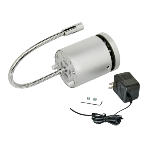
- Page 7 Section 1 ___________________________ SC-100 series...
- Page 8 MODEL: SC-100 AC INSTALLING MODEL #SC-100 Step 1. With the tool provided, remove the four (4) tamper-resistant screws located on the control plate. 2. Gently pull on the gooseneck to separate the control plate assembly from the main housing. WIRING DIAGRAM 3.
-
Page 9: Model #Sc-100
MODEL: SC-100 HG PARTITION (GLASS) 2.5MM HEADSET POWER LISTEN TALK MODEL #SC-100HG MUTE MUTE HAVEN TECHNOLOGY RIVERSIDE, CA HEADSET AC ADAPTER AC ADAPTER SIDE VIEW BOTTOM VIEW TITLE REV.A REV.E DRAWN BY: REV.B REV.F DATE: 4-14-03 MODEL #SC-100HG / #SC-100GT REV.C REV.G SHOP ORD.#... -
Page 10: Model #Sc-100H
MODEL: SC-100 H IMPORTANT! HEADSET GRASP HERE TO REMOVE HEADSET 2.5MM HEADSET POWER LISTEN TALK PLUG MUTE MUTE HAVEN TECHNOLOGY RIVERSIDE, CA AC ADAPTER IMPORTANT! DO NOT PULL HERE TO REMOVE HEADSET FROM BASE UNIT SIDE VIEW BOTTOM VIEW REV.A REV.E DRAWN BY: TITLE... - Page 11 MODEL: SC-100L - DC - Rechargeable Battery PARTITION (GLASS) 2.5MM HEADSET MODEL #SC-100L POWER LISTEN TALK MUTE MUTE HAVEN TECHNOLOGY RIVERSIDE, CA AC ADAPTER AC ADAPTER BOTTOM VIEW SIDE VIEW TITLE REV.A REV.E DRAWN BY: REV.B REV.F DATE: 4-14-03 REV.C REV.G SHOP ORD.# SHEET:...
- Page 12 SC-100L Battery Start-Up Procedures Questions? Do not adjust dials! Call us at (typical of two) 888-853-4643 or (951) 354-1800 To activate the battery circuit, move the toggle switch to the “ON” position. Do not adjust dials! Picture of batteries may not be representative of (typical of two) actual battery pack provided PLEASE READ BEFORE USING FOR THE FIRST TIME.
- Page 13 Section 2 ___________________________ SC-200 model SC-300 model SC-350 model...
- Page 14 Installation Summary SC-200/300 Step 1: Tools you will need • 11/32 nut driver, hollow shaft: to install 8-32 nuts on the window module. • Small flat head screw driver: : to install AC adapter wiring within the master unit. • Power drill and mounting hardware to mount the customer-side Remote Unit and Master Station (if desired).
- Page 15 Step 6: Connect AC adapter • Thread the AC adapter cable through the 0.25” hole in the backbox • Terminal #1 is “+” (white strip on the wire) Terminal #2 is “-“. Do not plug the adapter into the wall yet. •...
- Page 16 Installation Summary SC-350 Step 1: Tools you will need • 11/32 nut driver, hollow shaft: to install 8-32 nuts on the window module. • Small flat head screw driver: : to install AC adapter wiring within the master unit. Step 2: examine contents Each individual box contains the following: •...
- Page 17 RS-1 RS-1 REMOTE STATION DRAIN BLACK FACTORY WIRING BLACK WITH WHITE STRIPE FACTORY FURNISHED FIELD CABLE. CONNECT TO CORRESPONDING TERMINALS SC-350 AS SHOWN (CLASS II WIRING). BELDEN #87723 IN CONDUIT CA-1. MASTER STATION A/C ADAPTER PART #394086-1 MODEL # D41W120300-14/1 SC-350 MASTER STATION HAVEN...
- Page 18 Step 6: Connect AC adapter • Thread the AC adapter cable through the 0.25” hole in the backbox • Terminal #1 is “+” (white strip on the wire) Terminal #2 is “-“. Do not plug the adapter into the wall yet. •...
- Page 19 CUSTOMER SIDE (OUTSIDE) 8.00 SAFETY-COMM. 3.70 RIVERSIDE, CALIFORNIA WITH THE TOOL PROVIDED, REMOVE THE FOUR (4) TAMPER RESISTANT SCREWS FROM THE FACE PLATE. REVISION A DRAWN BY: TITLE DATE: REVISION B 7/21/99 FIELD INSTALLATION REVISION C SHOP ORD.# MODEL #SC-200 MASTER UNIT AND #SC-200, #SC-300 REMOTE UNIT SHEET: DRAWING NO: 5243B...
- Page 20 SUGGESTED MOUNTING HOLE CONFIGURATION 7.750 1.000 2.875 2.875 1.000 .750 1.500 3.000 .750 MOUNTING HOLES (X4) CABLE ENTRY HOLE BOTTOM VIEW STEP 1: DRILL FOUR MOUNTING HOLES IN THE BACK OR BOTTOM OF THE UNIT. STEP 2: DRILL 1/2" DIAMETER HOLE IN THE APPROXIMATE CENTER OF THE BACKBOX FOR CABLE ENTRY.
-
Page 21: Model #Sc-100L
MODEL: SC-200 REMOTE UNIT WIRING DIAGRAM TERM. BOARD MASTER UNIT AUDIO BOARD IN REAR MIC.SEN DRAIN J102 MIC.SEN R131 FACTORY FURNISHED FIELD CABLE. VOLUME VOLUME CONNECT TO CORRESPONDING TERMINALS R105 AS SHOWN (CLASS II WIRING). BELDEN #87723 FRONT SIDE VIEW VIEW 2.80 AC ADAPTER... -
Page 22: Model #Sc-200, #Sc-300
SAFETY-COMM. INSTALLATION COMPLETE MODEL # SC-200 MODEL # SC-300 INSTALLATION COMPLETE... -
Page 23: Model #Sc-300Hg
MODEL: SC-300HG NOTE FACTORY WIRING NOT SHOWN SEE PAGE 9 FOR WIRING DIAGRAM TITLE REVISION A DRAWN BY: REVISION B DATE: 8-8-02 HEADSET APPLICATION FOR MODEL #SC-300HG REVISION C SHOP ORD.# 5375B REVISION D DRAWING SIZE SHEET: OF: DRAWING NO:... -
Page 24: Model #Sc-350
MODEL: SC-350 INSTALLATION INSTRUCTIONS REAR VIEW OF RS-1 WINDOW MODULE Installing the Safety-Comm. : WITHOUT TERMINAL PLATE Step 1. With the tool provided, remove the four (4) tamper-resistant screws located on the backplate. 2. Gently pull on the backplate to separate the backplate assembly from the main window module. 3. - Page 25 MODEL: SC-350 INSTALLATION DIAGRAM REMOTE UNIT (RS-1) TERMINAL BOARD MASTER UNIT AUDIO BOARD WIRING DIAGRAM FACTORY WIRING IN REAR FACTORY FURNISHED FIELD CABLE. MIC.SEN TO OUTSIDE PLATE CONNECT TO CORRESPONDING TERMINALS (CLASS II WIRING). J102 BELDEN #87723 MIC.SEN R131 DRAIN TERMINAL BOARD VOLUME VOLUME...
- Page 26 Section 3 ___________________________ SC-600 model...
- Page 27 5 GANG BACK BOX REMOTE UNIT FURNISHED BY OTHERS. 2.50 BOTTOM VIEW FRONT VIEW NOTES: 1. CROSS MARK IS FOR REFERENCE ONLY DO NOT ETCHING OR ENGRAVE. 2. ALL LETTERINGS: SELECTIVE ANODIZING IN NAVY BLUE. LOGO: SELECTIVE ANODIZING IN DARK GREEN. INSTALLATION MODEL #SC-600 REMOTE UNIT...
- Page 28 5 GANG BACK BOX FURNISHED BY MASTER UNIT OTHERS 2.50 BOTTOM VIEW FRONT VIEW NOTES: 1. CROSS MARK IS FOR REFERENCE ONLY DO NOT ETCHING OR ENGRAVE. 2. ALL LETTERINGS: SELECTIVE ANODIZING IN NAVY BLUE. LOGO: SELECTIVE ANODIZING IN DARK GREEN. INSTALLATION MODEL #SC-600 MASTER UNIT...
- Page 29 PARTITION REMOTE UNIT MASTER UNIT SAFETY-COMM. SAFETY-COMM. MODEL #SC-600 MODEL #SC-600 FRONT VIEW FRONT VIEW SECTIONAL VIEW INSTALLATION OF MODEL #SC-600 MASTER AND REMOTE...
- Page 30 FACTORY INSTALLED WIRING (4 CIRCUIT) DRAIN SPEAKER REMOTE UNIT 4 CONDUCTOR CABLE WITH DRAIN WIRE REAR VIEW (SHIELDED TWISTED) FACTORY FURNISHED BELDEN #88723 FACTORY INSTALLED WIRING (4 CIRCUIT) J102 AUDIO BOARD SPEAKER MASTER UNIT REAR VIEW AC ADAPTER BOTTOM VIEW FRONT SIDE VIEW...
-
Page 31: Attention Users
Attention Users: Training/Operation tips Thank you for purchasing our Safety-Comm.® line of Box Office/Transaction Intercom Systems. After installation, please review this document in full. Understanding this material will help you operate the units more efficiently. • VOX operation: Box Office/Transaction intercoms on the market today employ VOX technology. This means that conversations are one-at-a-time, not full duplex like land-line telephone systems (where participants can talk and listen at the same time). - Page 32 NOTE: set volume control knobs to “3:00” postition before beginning. Safety-Comm. Field Calibration ® Questions? VR31 “master” or inside Call: (951) 354-1800 VR26 gooseneck dominance. DO NOT ADJUST! CONSULT THE FACTORY PRIOR TO ADJUST- MENT. VR131 remote/outside Symptom: conversation is “clipped”; conversations are cut short. Solution: FIRST: NOTE ORIGINAL POSITION OF THE POTENTIOMETERS.
-
Page 33: Warranty
Warranty Haven Technology Corporation (“HTC”) warrants to the original end-user of this product that it shall be free from defects in workmanship and materials for a period of twelve (12) months from the date of factory shipment. To obtain warranty service, a Return Materials Authorization (“RMA”) number must be issued by HTC.
Need help?
Do you have a question about the HAVEN SC-100 and is the answer not in the manual?
Questions and answers