Table of Contents
Advertisement
Quick Links
3 1/2 Digits Unbeatable Best Buy Multimeters with All-Ranges Protection
OPERATION MANUAL
1. SAFETY RULES
This meter is designed and tested in accordance with EN publication 61010-1, pollution
degree II and installation category (overvoltage category) II 600V.
This meter has been tested according to the following EC Directives
♦
89/336/EEC Electromagnetic Compatibility, EN61326
♦
73/23/EEC Product safety law of Low Voltage Directive, EN61010-1
This meter is designed to be indoor use at temperature 5°C to 40°C and altitude up to
2,000m.
To ensure that the meter is used safely, follow all safety and operating instructions in
this operation manual. If the meter is not used as described in this operation manual,
the safety features of this meter might be impaired.
2. INTERNATIONAL SYMBOLS
Important information
!
see manual
AC
DC
3. SPECIFICATIONS
3.1 General Specifications
Display
: 3 1/2 digit LCD with max. reading of 1999.
Polarity
: Automatic, (-) negative polarity indication.
Zero adjustment
: Automatic.
Over range indication
: Only the MSD "1" is displayed.
Power
: 1.5V AAA battery x 3
Dimension
: 85 (W) x 155 (H) x 40 (D) mm.
Net Weight
: Approx. 250g. (Including battery).
3.2 Electrical Specifications
Accuracies are ± (% of reading + number of least significant digits) at 23°C ± 5°C, <75% RH.
Range
Resolution
200mV
0.1mV
2V
1mV
DC Voltage
20V
0.01V
200V
0.1V
600V
1V
Range
Resolution
AC Voltage
200V
0.1V
600V
1V
Range
Resolution
20mA
0.01mA
DC Current
200mA
0.1mA
10A
(Optional)
0.1A
*
Range
Resolution
200Ω
0.1Ω
2kΩ
0.001kΩ
Resistance
20kΩ
0.01kΩ
200kΩ
0.1kΩ
2MΩ
0.001MΩ
Test Voltage
Diode Test
<3V
Test range
Continuity
Buzzer sounds when
Test
resistance value
<30Ω
Range
Phase Sequence
Indication
±
380ACV
10%
Live Wire
Verification Voltage
Output
Voltage
Square Waveform
Output
Approx. 3V
Diode
Continuity
Ground
Double insulation
Input
Accuracy
Impedance
600V DC/ACrms
±(1.0%+3)
10MΩ
Frequency
Accuracy
(Hz)
±(1.2%+3d)
40~400
600V DC/ACrms
Overload
Accuracy
Protection
±(1.2%+3d)
250V DC/ACrms
±(5.0%+3d)
Open circuit
Accuracy
voltage
250V DC/AC rms
±(1.2%+3d)
<1.0V
Test Current
Overload Protection
250V DC/AC rms
Approx. 1.6mA
Open circuit
Voltage
250V DC/AC rms
<3V
Phase Sequence Indication
Correct Phase Sequence
– Phase Sequence Light "ON"
Tested Voltage Range
100~250V
Frequency
Wave Form
Overload Protection
Square
250V DC/AC rms
50Hz
Wave
<30 sec.
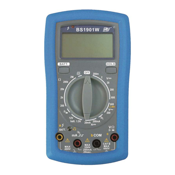
4. PANEL DESCRIPTIONS
1.
Live wire verification indication light
2.
LCD display
3.
Battery test key
4.
Multifunction selector
5.
HOLD key
6.
Phase verification indication light
7.
Input terminal
5. OPERATION
!
WARNING
1) When measuring voltage ensure that the
instrument is not connected or switched to a current or resistance, or battery test, or
diode/ continuity check range. Always ensure that the correct terminals are used for the
type of measurement to be made.
2) Use extreme care when measuring voltage above 50V, especially from sources where
high energy exists.
3) Avoid making connections to "live" circuits whenever possible.
4) When performing current measurements ensure that the circuit is not "live" before opening
it in order to connect the test leads.
5) Before performing resistance measurements or diode test, ensure that the circuit under
test is de-energised.
6) Always ensure that the correct function and range is selected. If in doubt about the correct
range, start with the highest and work downwards.
7) Extreme care should be taken when using the instrument to conjunction with a current
transformer connected to the terminals. High voltage may be produced at the terminals if
an open circuit occurs.
8) Ensure that the test leads and prods are in good condition with no damage to the
insulation.
Overload
9) Take care not to exceed the overload limits as given in the specifications.
Protection
5.1
DC and AC voltage measurement
1. Connect the black test lead to the "COM" terminal and red test lead to the "V" terminal.
2. Set the multifunction selector to desired DC V or AC V position and connect the test leads
across the source or load under measurement.
Overload
5.2
DC current measurement
Protection
1. Connect the black test lead to the "COM" terminal and red test lead to the "mA" terminal
for measurement up to 200mA.
2. Set the multifunction selector to desired current range position.
3. Connect the test leads in series with the current source to be measured.
4. When the tested current is above 100mA, the input voltage drop might above 1V; hence,
the test duration cannot exceed 15 seconds!
!
CAUTION: Max. input overload: 250V rms < 20sec.
5.3
Resistance measurement
1. Connect the black test lead to the "COM" terminal and red test lead to the "Ω" terminal.
Overload
2. Set the multifunction selector to desired resistance (Ω) range position.
Protection
3. Connect the test leads across the circuit to be tested.
!
CAUTION:
<30 sec.
5.4
Diode test
1. Connect the black test lead to the "COM" terminal and red test lead to the "
2. Set the multifunction selector to
3. Connect the black and red test leads to the cathode (-) and anode (+) ends of the diode
to be tested respectively.
<30 sec.
4. Read the forward voltage drop (junction) value from the display. When the forward biased
Overload
is open, the display will shows overload '1' .
protection
!
CAUTION: Max. input overload: 250V rms < 20sec.
<30 sec.
5.5
Phase Sequence Verification
1. Connect the red test lead to the "c" terminal, black test lead to "b" terminal and yellow test
lead to "a" terminal
2. Set the multifunction selector to "600V~/abc" range.
3. Connect yellow/black/red test lead to three-phase contact point, If the phase sequence
LED lights on, indicating the connection is in correct phase sequence.
4. If the phase sequence LED lights off, please swap black (b) and red (c) test leads, if the
LED remains off which means that there is a missing phase or wrong connection, please
use Live Wire Verification function to verify each phase again.
5.6
Live Wire Verification
1. Connect the red test lead to the "
black test lead to "COM" terminal and hold the black
test lead (please note: do not touch the test pin
and keep your hands away from the finger guard
of the test lead!)
2.
Set the multifunction selector to "600V~/abc"
range.
3. Use the red test lead to contact the live wire to
be tested. When there is a live wire, the Live Wire
Verification lights will turn on.
Ensure that the circuit to be tested is "dead".
Max. input overload : 250V rms < 20sec.
(same as
) position.
" terminal,
" terminal.
Advertisement
Table of Contents

Related Manuals for BST BS1901W


Summary of Contents for BST BS1901W
- Page 1 3 1/2 Digits Unbeatable Best Buy Multimeters with All-Ranges Protection OPERATION MANUAL 4. PANEL DESCRIPTIONS 1. SAFETY RULES This meter is designed and tested in accordance with EN publication 61010-1, pollution Live wire verification indication light degree II and installation category (overvoltage category) II 600V. LCD display This meter has been tested according to the following EC Directives ...
- Page 2 7. ACCESSORIES Continuity test 1. Connect the black test lead to the “COM” terminal and red test lead to the “ ” terminal. 2. Set the multifunction selector to (same as ) position. The accessories contained inside the packaging are the following: 3.
Need help?
Do you have a question about the BS1901W and is the answer not in the manual?
Questions and answers