Table of Contents
Advertisement
Quick Links
Advertisement
Table of Contents

Related Manuals for ASROCK Q270 Pro BTC+


Summary of Contents for ASROCK Q270 Pro BTC+
- Page 2 (including damages for loss of profits, loss of business, loss of data, interruption of business and the like), even if ASRock has been advised of the possibility of such damages arising from any defect or error in the documentation or product.
- Page 3 If you require assistance please call ASRock Tel : +886-2-28965588 ext.123 (Standard International call charges apply) The terms HDMI®...
- Page 4 ES OF ANY KIND WHETHER UNDER THIS AGREEMENT OR OTHERWISE, EVEN IF INTEL HAS BEEN ADVISED OF THE POSSIBILITY OF SUCH DAMAGES. LICENSE TO USE COMMENTS AND SUGGESTIONS. This Agreement does NOT obligate Licensee to provide Intel with comments or suggestions regarding the Software. However, if Licensee provides Intel with comments or suggestions for the modification, correction, improvement or enhancement of (a) the Software or (b) Intel products or processes that work with the Software, Licensee grants to Intel a non-exclusive, worldwide,...
-
Page 5: Table Of Contents
Onboard Headers and Connectors Smart Buttons PCIe Power Connector Installation Guide M.2_SSD (NGFF) Module Installation Guide 2.10 Special Features 2.10.1 Smart PCIe State Detection Chapter 3 Software and Utilities Operation Installing Drivers ASRock Live Update & APP Shop 3.2.1 UI Overview 3.2.2 Apps... - Page 6 3.2.3 BIOS & Drivers 3.2.4 Setting Enabling USB Ports for Windows® 7 Installation Chapter 4 UEFI SETUP UTILITY Introduction 4.1.1 UEFI Menu Bar 4.1.2 Navigation Keys Main Screen OC Tweaker Screen Advanced Screen 4.4.1 CPU Configuration 4.4.2 Chipset Configuration 4.4.3 Storage Configuration 4.4.4 Super IO Configuration 4.4.5 ACPI Configuration 4.4.6 USB Configuration...
-
Page 7: Chapter 1 Introduction
ASRock’s website without further notice. If you require technical support related to this motherboard, please visit our website for specific information about the model you are using. You may find the latest VGA cards and CPU support list on ASRock’s website as well. ASRock website http://www.asrock.com. -
Page 8: Specifications
1.2 Specifications Platform • ATX Form Factor • Solid Capacitor design • Supports 7 and 6 Generation Intel® Core i5/i3/Pentium®/ Celeron® Processors (Socket 1151) • Supports CPU up to 91W • Digi Power design • 6 Power Phase design • Supports Intel® Turbo Boost 2.0 Technology Chipset • Intel®... - Page 9 Q270 Pro BTC+ • Supports Auto Lip Sync, Deep Color (12bpc), xvYCC and HBR (High Bit Rate Audio) with HDMI 1.4 Port (Compliant HDMI monitor is required) • Supports HDCP 1.4 with HDMI 1.4 Port • Supports Full HD 1080p Blu-ray (BD) playback with HDMI 1.4 Port Audio • 7.1 CH HD Audio (Realtek ALC897 Audio Codec)
- Page 10 * To install Windows® 7 OS, a modified installation disk with xHCI drivers packed into the ISO file is required. Please refer to page 35 for more detailed instructions. * For the updated Windows® 10 driver, please visit ASRock’s website for details: http://www.asrock.com...
- Page 11 • ErP/EuP Ready (ErP/EuP ready power supply is required) * For detailed product information, please visit our website: http://www.asrock.com Please realize that there is a certain risk involved with overclocking, including adjusting the setting in the BIOS, applying Untied Overclocking Technology, or using third-party overclocking tools.
-
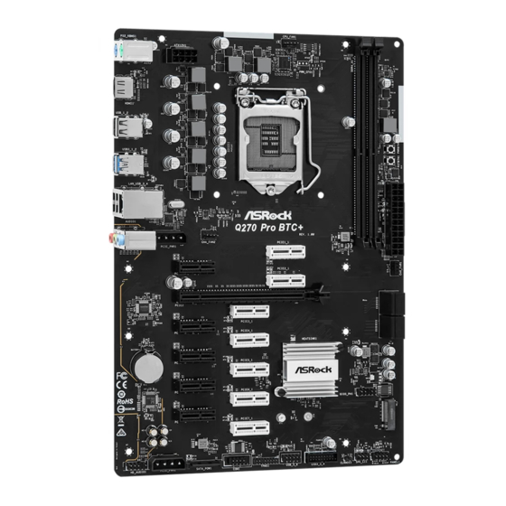
Page 12: Motherboard Layout
1.3 Motherboard Layout... - Page 13 Q270 Pro BTC+ No. Description ATX 12V Power Connector (ATX12V1) CPU Fan Connector (CPU_FAN1) 2 x 288-pin DDR4 DIMM Slots (DDR4_A1, DDR4_B1) Power Button (PWRBTN1) Reset Button (RSTBTN1) ATX Power Connector (ATXPWR1) Chassis Fan Connector (CHA_FAN1) SATA3 Connector (SATA3_0) (Upper), SATA3 Connector (SATA3_1) (Lower) SATA3 Connector (SATA3_2) (Upper), SATA3 Connector (SATA3_3) (Lower) System Panel Header (PANEL1) Chassis Intrusion and Speaker Header (SPK_CI1)
-
Page 14: I/O Panel
1.4 I/O Panel No. Description No. Description PS/2 Mouse Port USB 2.0 Ports (USB_3_4) LAN RJ-45 Port* USB 3.2 Gen1 Ports (USB3_1_2) Line In (Light Blue)** USB 2.0 Ports (USB_1_2) Front Speaker (Lime)** HDMI Port Microphone (Pink)** PS/2 Keyboard Port * There are two LEDs on the LAN port. -
Page 15: Chapter 2 Installation
Q270 Pro BTC+ Chapter 2 Installation This is an ATX form factor motherboard. Before you install the motherboard, study the configuration of your chassis to ensure that the motherboard fits into it. Pre-installation Precautions Take note of the following precautions before you install motherboard components or change any motherboard settings. -
Page 16: Installing The Cpu
2.1 Installing the CPU 1. Before you insert the 1151-Pin CPU into the socket, please check if the PnP cap is on the socket, if the CPU surface is unclean, or if there are any bent pins in the socket. Do not force to insert the CPU into the socket if above situation is found. Otherwise, the CPU will be seriously damaged. - Page 17 Q270 Pro BTC+...
- Page 18 Please save and replace the cover if the processor is removed. The cover must be placed if you wish to return the motherboard for after service.
-
Page 19: Installing The Cpu Fan And Heatsink
Q270 Pro BTC+ 2.2 Installing the CPU Fan and Heatsink... -
Page 20: Installing Memory Modules (Dimm)
2.3 Installing Memory Modules (DIMM) This motherboard provides two 288-pin DDR4 (Double Data Rate 4) DIMM slots, and supports Dual Channel Memory Technology. 1. For dual channel configuration, you always need to install identical (the same brand, speed, size and chip-type) DDR4 DIMM pairs. 2. - Page 21 Q270 Pro BTC+...
-
Page 22: Expansion Slots (Pci Express Slots)
2.4 Expansion Slots ( Express Slots) There are 13 PCI Express slots on the motherboard. Before installing an expansion card, please make sure that the power supply is switched off or the power cord is unplugged. Please read the documentation of the expansion card and make necessary hardware settings for the card before you start the installation. -
Page 23: Jumpers Setup
Q270 Pro BTC+ 2.5 Jumpers Setup The illustration shows how jumpers are setup. When the jumper cap is placed on the pins, the jumper is “Short”. If no jumper cap is placed on the pins, the jumper is “Open”. Clear CMOS Jumper (CLRMOS1) 2-pin Jumper (see p.6, No. -
Page 24: Onboard Headers And Connectors
2.6 Onboard Headers and Connectors Onboard headers and connectors are NOT jumpers. Do NOT place jumper caps over these headers and connectors. Placing jumper caps over the headers and connectors will cause permanent damage to the motherboard. System Panel Header Connect the power PLED+ PLED-... - Page 25 Q270 Pro BTC+ Serial ATA3 Connectors These four SATA3 Right Angle: connectors support SATA (SATA3_0: data cables for internal see p.6, No. 8) (Upper) storage devices with up to (SATA3_1: 6.0 Gb/s data transfer rate. see p.6, No. 8) (Lower) (SATA3_2: see p.6, No.
- Page 26 Front Panel Audio Header This header is for PRESENCE# (9-pin HD_AUDIO1) MIC_RET connecting audio devices OUT_RET (see p.6, No. 19) to the front audio panel. OUT2_L J_SENSE OUT2_R MIC2_R MIC2_L 1. High Definition Audio supports Jack Sensing, but the panel wire on the chassis must support HDA to function correctly.
- Page 27 Q270 Pro BTC+ ATX Power Connector This motherboard pro- (24-pin ATXPWR1) vides a 24-pin ATX power (see p.6, No. 6) connector. To use a 20-pin ATX power supply, please plug it along Pin 1 and Pin ATX 12V Power This motherboard pro- Connector vides an 8-pin ATX 12V (8-pin ATX12V1)
-
Page 28: Smart Buttons
2.7 Smart Buttons The motherboard has two smart buttons: Power Button and Reset Button. Power Button Power Button allows users (PWRBTN1) to quickly turn on/off the (see p.6, No. 4) system. Reset Button Reset Button allows (RSTBTN1) users to quickly reset the (see p.6, No. -
Page 29: Pcie Power Connector Installation Guide
Q270 Pro BTC+ 2.8 PCIe Power Connector Installation Guide The two extra 4-pin power connectors on this motherboard offer more power for your graph- ics cards. They provide stable voltages and greatly reduce the risks of burning your mother- board or graphics cards. When more than three graphics cards are installed, be sure to install the PSU’s 4-pin power cables to the 4-pin power connectors (PCIE_PWR) on your motherboard;... -
Page 30: M.2_Ssd (Ngff) Module Installation Guide
2.9 M.2_SSD (NGFF) Module Installation Guide The M.2, also known as the Next Generation Form Factor (NGFF), is a small size and versatile card edge connector that aims to replace mPCIe and mSATA. The M.2 Socket (M2_1) supports type 2260/2280 M.2 SATA3 6.0 Gb/s module. Installing the M.2_SSD (NGFF) Module Step 1 Prepare a M.2_SSD (NGFF) module... - Page 31 Q270 Pro BTC+ Step 3 Move the standoff based on the module type and length. The standoff is placed at the nut location B by default. Skip Step 3 and 4 and go straight to Step 5 if you are going to use the default nut.
- Page 32 SATA Transcend TS256GMTS800-256GB Transcend SATA Transcend TS64GMTS400-64GB V-Color SATA V-Color 120G V-Color SATA V-Color 240G SATA WD BLUE WDS100T1B0B-00AS40 SATA WD GREEN WDS240G1G0B-00RC30 For the latest updates of M.2_SSD (NFGG) module support list, please visit our website for details: http://www.asrock.com...
-
Page 33: Special Features
Q270 Pro BTC+ 2.10 Special Features 2.10.1 Smart PCIe State Detection This motherboard has included a smart way to show the status of every graphics card. While the system is booting, the Power-On, Self-Test (POST) screen will show the status of the graphics cards that were installed on the motherboard. -
Page 34: Chapter 3 Software And Utilities Operation
Chapter 3 Software and Utilities Operation 3.1 Installing Drivers The Support CD that comes with the motherboard contains necessary drivers and useful utilities that enhance the motherboard’s features. Running The Support CD To begin using the support CD, insert the CD into your CD-ROM drive. The CD automatically displays the Main Menu if “AUTORUN”... -
Page 35: Asrock Live Update & App Shop
Double-click on your desktop to access ASRock Live Update & APP Shop utility. *You need to be connected to the Internet to download apps from the ASRock Live Update & APP Shop. 3.2.1 UI Overview Category Panel Hot News... -
Page 36: Apps
3.2.2 Apps When the "Apps" tab is selected, you will see all the available apps on screen for you to download. Installing an App Step 1 Find the app you want to install. The most recommended app appears on the left side of the screen. The other various apps are shown on the right. - Page 37 Q270 Pro BTC+ Step 3 If you want to install the app, click on the red icon to start downloading. Step 4 When installation completes, you can find the green "Installed" icon appears on the upper right corner. To uninstall it, simply click on the trash can icon *The trash icon may not appear for certain apps.
- Page 38 Upgrading an App You can only upgrade the apps you have already installed. When there is an available new version for your app, you will find the mark of "New Version" appears below the installed app icon. Step 1 Click on the app icon to see more details. Step 2 Click on the yellow icon to start upgrading.
-
Page 39: Bios & Drivers
Q270 Pro BTC+ 3.2.3 BIOS & Drivers Installing BIOS or Drivers When the "BIOS & Drivers" tab is selected, you will see a list of recommended or critical updates for the BIOS or drivers. Please update them all soon. Step 1 Please check the item information before update. -
Page 40: Setting
3.2.4 Setting In the "Setting" page, you can change the language, select the server location, and determine if you want to automatically run the ASRock Live Update & APP Shop on Windows startup. -
Page 41: Enabling Usb Ports For Windows® 7 Installation
Requirements A Windows® 7 installation disk or USB drive • A Windows® PC • Win7 USB Patcher (included in the ASRock Support CD or downloaded from • website) Scenarios You have an ODD and PS/2 ports: If there is an optical disc drive, PS/2 ports and PS/2 Keyboard or mouse on your computer, you can skip the instructions below and go ahead to install Windows®... - Page 42 Instructions Step 1 Insert the Windows® 7 installation disk or USB drive to your system. Step 2 Extract the tool (Win7 USB Patcher) and launch it. Step 3 Select how you want to install Windows 7 later. Step 4 Locate your Win7 source folder or your ISO file.
- Page 43 Q270 Pro BTC+ Step 5 Select the USB storage, compact disk or destination folder for the new Windows 7 installation file. Step 6 Click “Start” to begin. Step 7 Now you are able to install Windows® 7 on Intel® new processors with the new burned CD. Or please use the patched ISO image to make an OS USB drive to install the OS.
-
Page 44: Chapter 4 Uefi Setup Utility
Chapter 4 UEFI SETUP UTILITY 4.1 Introduction This section explains how to use the UEFI SETUP UTILITY to configure your system. You may run the UEFI SETUP UTILITY by pressing <F2> or <Del> right after you power on the computer, otherwise, the Power-On-Self-Test (POST) will continue with its test routines. -
Page 45: Navigation Keys
Q270 Pro BTC+ 4.1.2 Navigation Keys Use < > key or < > key to choose among the selections on the menu bar, and use < > key or < > key to move the cursor up or down to select items, then press <Enter>... -
Page 46: Main Screen
4.2 Main Screen When you enter the UEFI SETUP UTILITY, the Main screen will appear and display the system overview. The availability and location of BIOS settings can be different for different models and BIOS versions. -
Page 47: Oc Tweaker Screen
Q270 Pro BTC+ 4.3 OC Tweaker Screen In the OC Tweaker screen, you can set up overclocking features. Because the UEFI software is constantly being updated, the following UEFI setup screens and descriptions are for reference purpose only, and they may not exactly match what you see on your screen. - Page 48 Intel Speed Shift Technology Enable/Disable Intel Speed Shift Technology support. Enabling will expose the CPPC v2 interface to allow for hardware controlled P-states. Long Duration Power Limit Configure Package Power Limit 1 in watts. When the limit is exceeded, the CPU ratio will be lowered after a period of time.
- Page 49 Q270 Pro BTC+ Primary Timing CAS# Latency (tCL) The time between sending a column address to the memory and the beginning of the data in response. RAS# to CAS# Delay and Row Precharge (tRCDtRP) RAS# to CAS# Delay : The number of clock cycles required between the opening of a row of memory and accessing columns within it.
- Page 50 Write to Read Delay (tWTR_S) The number of clocks between the last valid write operation and the next read command to the same internal bank. Read to Precharge (tRTP) The number of clocks that are inserted between a read command to a row pre- charge command to the same rank.
- Page 51 Q270 Pro BTC+ tRDWR_dr Configure between module read to write delay. tRDWR_dd Configure between module read to write delay. tWRRD_sg Configure between module write to read delay. tWRRD_dg Configure between module write to read delay. tWRRD_dr Configure between module write to read delay. tWRRD_dd Configure between module write to read delay.
- Page 52 CPU Core/Cache Load-Line Calibration helps prevent CPU Core/Cache voltage droop when the system is under heavy loading. CPU GT Voltage Configure the voltage for the integrated GPU. CPU GT Load-Line Calibration GT Load-Line Calibration helps prevent integrated GPU voltage droop when the system is under heavy load.
-
Page 53: Advanced Screen
Q270 Pro BTC+ 4.4 Advanced Screen In this section, you may set the configurations for the following items: CPU Configuration, Chipset Configuration, Storage Configuration, Super IO Configura- tion, ACPI Configuration, USB Configuration and Trusted Computing. Setting wrong values in this section may cause the system to malfunction. UEFI Configuration Active Page on Entry Select the default page when entering the UEFI setup utility. -
Page 54: Cpu Configuration
4.4.1 CPU Configuration Intel Hyper Threading Technology Intel Hyper Threading Technology allows multiple threads to run on each core, so that the overall performance on threaded software is improved. Active Processor Cores Select the number of cores to enable in each processor package. CPU C States Support Enable CPU C States Support for power saving. - Page 55 Q270 Pro BTC+ Package C State Support Enable CPU, PCIe, Memory, Graphics C State Support for power saving. CFG Lock This item allows you to disable or enable the CFG Lock. CPU Thermal Throttling Enable CPU internal thermal control mechanisms to keep the CPU from overheat- ing.
-
Page 56: Chipset Configuration
4.4.2 Chipset Configuration Primary Graphics Adapter Select a primary VGA. Top Of Lower Usable Dram Maximum Value of TOLUD. Dynamic assignment would adjust TOLUD automatically based on largest MMIO length of installed graphic controller. Above 4G Decoding Enable or disable 64bit capable Devices to be decoded in Above 4G Address Space (only if the system supports 64 bit PCI decoding). - Page 57 Q270 Pro BTC+ PCIE2 Link Speed Select the link speed for PCIE2. PCIE2_1 Link Speed Select the link speed for PCIE2_1. PCIE3 Link Speed Select the link speed for PCIE3. PCIE3_1 Link Speed Select the link speed for PCIE3_1. PCIE4 Link Speed Select the link speed for PCIE4.
- Page 58 This option enables/disables the ASPM support for all PCH PCIE devices. DMI ASPM Support This option enables/disables the control of ASPM on CPU side of the DMI Link. PCH DMI ASPM Support This option enables/disables the ASPM support for all PCH DMI devices. IOAPIC 24-119 Entries I/O APICs contain a redirection table, which is used to route the interrupts it receives from peripheral buses to one or more local APICs.
-
Page 59: Storage Configuration
Q270 Pro BTC+ 4.4.3 Storage Configuration SATA Controller(s) Enable/disable the SATA controllers. SATA Controller Speed Indicates the maximum speed the SATA controller can support. SATA Mode Selection AHCI: Supports new features that improve performance. RAID: Combine multiple disk drives into a logical unit. SATA Aggressive Link Power Management SATA Aggressive Link Power Management allows SATA devices to enter a low power state during periods of inactivity to save power. -
Page 60: Super Io Configuration
4.4.4 Super IO Configuration Serial Port Enable or disable the Serial port. Serial Port Address Select the address of the Serial port. -
Page 61: Acpi Configuration
Q270 Pro BTC+ 4.4.5 ACPI Configuration Suspend to RAM Select disable for ACPI suspend type S1. It is recommended to select auto for ACPI S3 power saving. ACPI HEPT Table Enable the High Precision Event Timer for better performance. PS/2 Keyboard Power On Allow the system to be waked up by a PS/2 Keyboard. - Page 62 USB Mouse Power On Allow the system to be waked up by an USB mouse.
-
Page 63: Usb Configuration
Q270 Pro BTC+ 4.4.6 USB Configuration Legacy USB Support Enable or disable Legacy OS Support for USB 2.0 devices. If you encounter USB compatibility issues it is recommended to disable legacy USB support. Select UEFI Setup Only to support USB devices under the UEFI setup and Windows/Linux operating systems only. -
Page 64: Trusted Computing
4.4.7 Trusted Computing Security Device Support Enable or disable BIOS support for security device. -
Page 65: Tools
Save UEFI files in your USB storage device and run Instant Flash to update your UEFI. Internet Flash - DHCP (Auto IP), Auto ASRock Internet Flash downloads and updates the latest UEFI firmware version from our servers for you. Please setup network configuration before using Internet Flash. -
Page 66: Hardware Health Event Monitoring Screen
4.6 Hardware Health Event Monitoring Screen This section allows you to monitor the status of the hardware on your system, including the parameters of the CPU temperature, motherboard temperature, fan speed and voltage. CPU Fan 1 Setting Select a fan mode for CPU Fan 1, or choose Customize to set 5 CPU temperatures and assign a respective fan speed for each temperature. - Page 67 Q270 Pro BTC+ Chassis Fan 1 Step Down Set the value of Chassis Fan 1 Step Down. Chassis Fan 2 Setting Select a fan mode for Chassis Fan 2, or choose Customize to set 5 CPU temperatures and assign a respective fan speed for each temperature. Chassis Fan 2 Temp Source Select a fan temperature source for Chassis Fan 2.
-
Page 68: Security Screen
4.7 Security Screen In this section you may set or change the supervisor/user password for the system. You may also clear the user password. Supervisor Password Set or change the password for the administrator account. Only the administrator has authority to change the settings in the UEFI Setup Utility. Leave it blank and press enter to remove the password. -
Page 69: Boot Screen
Q270 Pro BTC+ 4.8 Boot Screen This section displays the available devices on your system for you to configure the boot settings and the boot priority. Fast Boot Fast Boot minimizes your computer's boot time. In fast mode you may not boot from an USB storage device. - Page 70 Full Screen Logo Enable to display the boot logo or disable to show normal POST messages. AddOn ROM Display Enable AddOn ROM Display to see the AddOn ROM messages or configure the AddOn ROM if you've enabled Full Screen Logo. Disable for faster boot speed. Boot Failure Guard Message If the computer fails to boot for a number of times the system automatically restores the default settings.
- Page 71 Q270 Pro BTC+ Select UEFI only to run those that support UEFI option ROM only. Select Legacy only to run those that support legacy option ROM only. Select Do not launch to not execute both legacy and UEFI option ROM. Launch Video OpROM Policy Select UEFI only to run those that support UEFI option ROM only.
-
Page 72: Exit Screen
4.9 Exit Screen Save Changes and Exit When you select this option the following message, “Save configuration changes and exit setup?” will pop out. Select [OK] to save changes and exit the UEFI SETUP UTILITY. Discard Changes and Exit When you select this option the following message, “Discard changes and exit setup?”... - Page 73 Contact Information If you need to contact ASRock or want to know more about ASRock, you’re welcome to visit ASRock’s website at http://www.asrock.com; or you may contact your dealer for further information. For technical questions, please submit a support request form at http://www.asrock.com/support/tsd.asp...
- Page 74 DECLARATION OF CONFORMITY Per FCC Part 2 Section 2.1077(a) Responsible Party Name: ASRock Incorporation Address: 13848 Magnolia Ave, Chino, CA91710 Phone/Fax No: +1-909-590-8308/+1-909-590-1026 hereby declares that the product Product Name : Motherboard Q270 Pro BTC+ Model Number : Conforms to the following speci cations:...
- Page 75 EU Declaration of Conformity For the following equipment: Motherboard (Product Name) Q270 Pro BTC+ / ASRock (Model Designation / Trade Name) ASRock Incorporation (Manufacturer Name) 2F., No.37, Sec. 2, Jhongyang S. Rd., Beitou District, Taipei City 112, Taiwan (R.O.C.) (Manufacturer Address) EMC —Directive 2014/30/EU (from April 20th, 2016)
Need help?
Do you have a question about the Q270 Pro BTC+ and is the answer not in the manual?
Questions and answers