
Summary of Contents for Deviser TC701B
- Page 1 TC701B Ethernet Test Module Operation Manual Ver1.31 Deviser Part No.: TC701B © Tianjin Deviser Electronics Instrument Co., Ltd. All rights reserved. Printed in CHINA, July. 2013.
- Page 3 Conventions This manual has the following conventions for presenting information. WARNING: A warning alerts you any condition that could cause personal injury. CAUTION: A caution alerts you any condition that could cause a mechanical failure or potential loss of data. Make sure the AC power supply voltage meets the equipment requirements;...
- Page 4 (shocking, dropping, and etc.). C. Defects caused by unauthorized repair. D. Defects caused by the instrument worked beyond the required technology specification. Updates Updates, if any, can be downloaded from the Deviser website at: http://www.deviserinstruments.com...
-
Page 5: Table Of Contents
Index 1.Introduction ··································································· 1 2.Basic Features ······························································· 3 2.1 Front Panel ································································ 3 2.2 Module Function Indicators ··········································· 4 3. Basic Operation ····························································· 5 3.1 Module Startup ··························································· 5 3.2 The Main Interface ······················································ 5 3.2.1 Main Function Area ················································ 5 3.2.2 Function Buttons Area ············································... - Page 6 4.3 Configurations ···························································· 9 4.3.1 Physical Layer Configurations ·································· 9 4.3.2 SFP Information ·················································· 10 4.3.3 Data Link Layer Configurations ······························· 10 4.3.4 Network Layer Configurations ································· 11 4.4 Instructions of Status Bar ············································ 15 4.5 Test Mode································································ 15 4.5.1 Dual Mode ························································· 15 4.5.2 Remote Loopback Mode ·······································...
- Page 7 5.2 Options ··································································· 22 5.2.1 Test Mode ·························································· 22 5.2.2 Throughput························································· 22 5.2.3 Latency ····························································· 23 5.2.4 FL (Frame Loss) ·················································· 24 5.2.5 Back-to-Back ······················································ 24 5.2.6 Global Setup ······················································ 25 5.2.7 Frame Distribution ··············································· 25 5.3 Result ····································································· 27 5.3.1 Summary ···························································...
- Page 8 6.5.2 Service Configuration Test ····································· 40 6.5.3 Service Performance Test······································ 42 7. BERT ·········································································· 45 7.1 Options ··································································· 45 7.2 Result ····································································· 46 8. Traffic Generation & Monitoring ····································· 48 8.1 Options ··································································· 48 8.2 Flow ······································································· 48 8.2.1 Common Stream Configurations ····························· 48 8.2.2 Main Flow(Flow 1)Stream Configurations ··············...
- Page 9 10.2.1 Summary ···························································· 62 11. Other Funtions ··························································· 64 11.1 Tools ····································································· 64 11.1.1 Ping Test ·························································· 64 11.1.2 Traceroute Test ·················································· 67 11.2 File Management ····················································· 69 11.3 Information ····························································· 70 11.4 Contact Us ····························································· 70 11.5 Update ·································································· 71 12.
-
Page 11: Introduction
RFC2544 test and Y.1564 test. Meanwhile, it also supports standard 10Base-T, 100Base-T, 1000Base-T and 1000Base-X Ethernet ports. The TC701B provides a comprehensive offering of test to the Ethernet maintainer with accurate data such as throughput, data rate, frame loss rate, bit error rate, number of transimiting or receiving packets/bytes and etc. - Page 12 TC701B Ethernet Test Module Operation Manual NOTE: 1.Please read ‘FC-1 high-performance portable platform operation manual’ before this specifications. 2.Please charge the FC-1 high-performance portable platform before the first use of the device.
-
Page 13: Basic Features
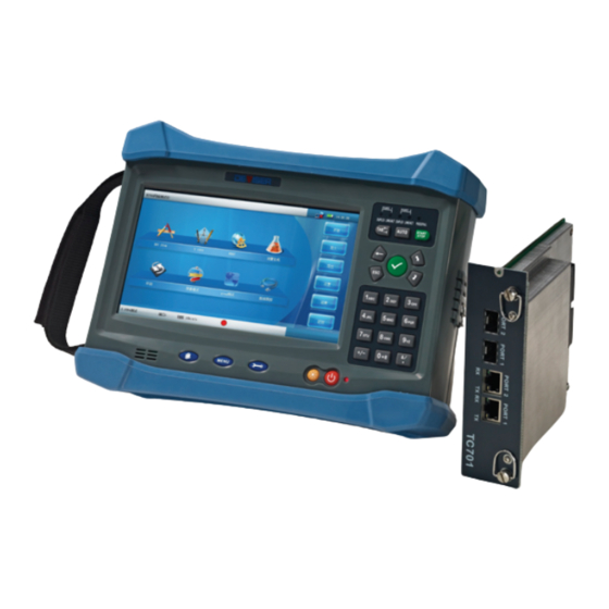
TC701B Ethernet Test Module Operation Manual 2.Basic Features 2.1 Front Panel Figure1 Front Panel Panel fixed screw hold PORT 2 SFP optical interface Heat radiation holes PORT 1 SFP optical interface PORT 1 RJ45 interface PORT 2 RJ45 interface Heat radiation holes... -
Page 14: Module Function Indicators
TC701B Ethernet Test Module Operation Manual 2.2 Module Function Indicators Module function indicators of TC701B Ethernet test module is on the right corner of FC-1 high-promance and portable platform. Figure 2 Module Function Indicators PORT 1 link state indicator, green means link-on. -
Page 15: Basic Operation
Press button in the apps-list area to start TC701B App, the touch screen displays startup screen as follows. Figure 3 TC701B App Startup Screen 3.2 The Main Interface... -
Page 16: Function Buttons Area
: Minimize button, it will switch to the interface of FC-1 portable high-performance platform when press this button. TC701B App would run in the background. : Quit button, it will display ‘Confirm Exit? ’ dialog box if pressing this button. Confirm to quit TC701B App and return to FC-1 interface. -
Page 17: General Operation
4. General Operation 4.1 Main Test Interface Press button in TC701B App main interface to enter the main test interface. There are six buttons in the main test interface that represent ‘RFC 2544’, ‘Y.1564’, ‘BERT’, ‘Traffic Gen. &Mon.’, ‘LoopBack’ and ‘Through Mode’. -
Page 18: Configurations
TC701B Ethernet Test Module Operation Manual 4.2.3 Configurations It will firstly enter the configuration interface when we start some kind of test. When the test has not begun , press the Setup button to lead into the configuration interface. The test configuration interface has many tabs.They are separated as ‘PHY’, ‘MAC’, ‘NET’, ‘OPT’... -
Page 19: Report Generation
When some kinds of tests are stopped or completely done, it will display a dialog to confirm whether TC701B generates a report or not . The device will save the result data in pdf format if we select ‘Yes’ . -
Page 20: Sfp Information
TC701B Ethernet Test Module Operation Manual Figure 6 Physically Layer Configurations NOTE:Throughout mode support two ports; and the ports are interconnection. Changing the settings of port1 could lead to changes of settings related to port2. 4.3.2 SFP Information This interface display parameters of the two SFP/SFP+ optical modules in real-time, which include ‘Module ID’, ‘Vendor Name’, ‘Part Number’,... -
Page 21: Network Layer Configurations
TC701B Ethernet Test Module Operation Manual from 00:00:00:00:00:00 to FF: FF: FF: FF: FF: FF. 3. Resolved MAC: Enable or Disabled Resolved MAC Address. When enabled, an ARP request is sent to the network to retrieve the MAC Address corresponding to the selected IP address for IPv4. When... - Page 22 TC701B Ethernet Test Module Operation Manual NOTE: If DHCP is enabled, all parameters are set to the values obtained from DHCP. If disable DHCP, IP address and subnet mask can be configurated; when enable DHCP, the default gateway is obtained from DHCP.
- Page 23 TC701B Ethernet Test Module Operation Manual 13) DEST UDP Port No: Enter the Destination UDP Port. The accepted range is from 0 to 65535. Figure 9 IPv4 Network Layer Configurations 2. IPv6 configurations 1) IP Version is selected as IPv6.
- Page 24 TC701B Ethernet Test Module Operation Manual the Link-Local address interface ID and the prefix obtained from the router advertisements. If no Interface ID has been obtained for the Link Local Address, the Global address will not be generated. Static: Allows entering the IP Address.
-
Page 25: Instructions Of Status Bar
‘dual mode’ and ‘remote loopback mode’. 4.5.1 Dual Mode In this mode, we need two TC701B to conduct a test, including dual RFC2544 test and dual Y.1564 test. One TC701B works in local mode and the other one works in remote mode. -
Page 26: Remote Loopback Mode
TC701B Ethernet Test Module Operation Manual 4.5.2 Remote Loopback Mode In this mode, we need a local TC701B and a remote loopback device to start a test. We can perform single RFC2544 test and single Y.1564 test. 4.6 Search the Remote Device 4.6.1 Introduction... -
Page 27: Manually Selection
TC701B Ethernet Test Module Operation Manual 4.6.3 Manually Selection We can control the TC701B with specific IP address to work in this mode. Enter the IP address of remote TC701B to ‘Target IP Address’ text box. Press ‘Refresh Status’ button to make it in use. Select the mode in the ‘Remote Capability’... - Page 28 Pause Time. Total: Displays the total number of valid flow control frames received including Abort Frames RX. When TC701B works in throughout mode, the interface will display ‘p1->p2’(port1 to port2) and ‘p2->p1’(port2 to port1) statistics data separately.
-
Page 29: Warning/Error
5) Runt: The number of received frames that are smaller than 64 bytes with an invalid FCS. 6) Undersize: The number of received frames smaller than 64 bytes with a valid FCS. When TC701B works in throughout mode, the interface will display... -
Page 30: Recorder
TC701B Ethernet Test Module Operation Manual ‘p1->p2’(port1 to port2) and ‘p2->p1’(port2 to port1) statistics data separately. Figure 15 Result Interface (Warning/Error) 4.7.3 Recorder The recorder records start time, end time, warning time and error time of the current test. Figure 16 Result Interface (Recorder) -
Page 31: Rfc 2544
TC701B Ethernet Test Module Operation Manual 5. RFC 2544 5.1 RFC 2544 Introduction RFC 2544 protocol is raised by the RFC organization for evaluation of the Network interconnection devices (firewall, IDS, Switch and etc.). It includes four main tests as follows: 5.1.1 Throughput... -
Page 32: Back-To-Back
TC701B Ethernet Test Module Operation Manual (( input_count - output_count ) * 100 ) / input_count 5.1.4 Back-to-Back Send a burst of frames with minimum inter-frame gaps to the DUT and count the number of frames forwarded by the DUT. If the count of transmitted frames is equal to the number of frames forwarded the length of the burst is increased and the test reruns. -
Page 33: Latency
TC701B Ethernet Test Module Operation Manual throughput test which should be done to verify DUT, range from 1 to 50. When the test mode is set dual mode, ‘Max. Rate’ and ‘Threshold’ configuration is separate for different direction: Local to Remote (L->R), Remote to Local(R->L). -
Page 34: Fl (Frame Loss)
TC701B Ethernet Test Module Operation Manual 5.2.4 FL (Frame Loss) If select ‘Enable’, Frame Loss test will starts or RFC 2544 would not run a frame loss test. When it selects ‘Time (MM:SS)’ of ‘Test Duration’, frame loss test will last for a set-fixed time, while selects ‘Frame(FR.)’ , frame loss test will not finished until a set-fixed number of frames have been transmitted. -
Page 35: Global Setup
TC701B Ethernet Test Module Operation Manual Figure 21 Back-to-Back Configurations 5.2.6 Global Setup 1. Pass/Fail Verdict:Enable/disabled the Pass/Fail Verdict. 2. Rate Unit: Allow the selection of the rate unit. That will be used to display the rate setting values. Choices are ‘%’ and ‘Mbit/s’. - Page 36 TC701B Ethernet Test Module Operation Manual Figure 23 Frame Distribution Configurations (RFC 2544) Frame Distribution can also be configurated as user-defined. In this mode, user can set different frame sizes (up to 7 different sizes), this mode supports 9600-size jumbo frame. The minimal frame size that this...
-
Page 37: Result
TC701B Ethernet Test Module Operation Manual 5.3 Result 5.3.1 Summary When the RFC 2544 test is running, a summary of the results as well as the detailed results per subtest is collected. The Summary results page displays the progress of each subtest. The progress per subtest is monitored and updated on a per second basis. -
Page 38: Graphic Display
TC701B Ethernet Test Module Operation Manual 5.3.2 Graphic Display Press ‘Total’ button to view the histogram of all four RFC 2544 test results. Press some kinds of test button to view the related histogram. In dual mode, when viewing the histogram as a whole, all histogram reflects the test results which are from local to remote (L->R). - Page 39 TC701B Ethernet Test Module Operation Manual Figure 28 RFC 2544 Result (Latency) Figure 29 RFC 2544 Result (Frame Loss) Figure 30 RFC 2544 Result (Back-to-Back)
-
Page 40: Introduction
TC701B Ethernet Test Module Operation Manual 6. Y.1564 6.1 Y.1564 Introduction 6.1.1 Service Configuration Test The purpose of this test is to verify the correctness of every service network configuration before starting a long-term-test (Network Performance Test). In order to test the network configuration, a ramp will be generated for each configured service. - Page 41 TC701B Ethernet Test Module Operation Manual the duration of each ramp step. It can be figured out according to step time and the number of steps each ramp. 2) Select the ‘SVC PERF Test’ check box, and then we can start service performance test, and set the duration time of the test in the following configuration.
-
Page 42: Service
TC701B Ethernet Test Module Operation Manual 6.3 Service 6.3.1 Service Configurations The Service Configuration page allows configuring the services from 1 to 10 and selecting the service profiles for different services such as voice, video, and data. 1. Service Name: The Service Name displays and allows modifying the service name. - Page 43 3-layer vlan Table 2 Minimal Frame Size in Y.1564 Test 4. Direction: This configuration is available when TC701B is in dual mode. The choices are ‘Local to Remote’ and ‘Remote to Local’ that you can set different SLA parameters to different directions.
- Page 44 TC701B Ethernet Test Module Operation Manual Note: Up to 10 services can be enabled one after another, as long as the total configured CIR is less than or equal to Line Rate. For example, if the first service is using the full bandwidth available (that is, Configured CIR = Line Rate), then no other service can be enabled.
-
Page 45: Mac Configurations
Figure 32 Y.1564 Configurations 6.3.2MAC Configurations 1. Direction:This configuration is available when TC701B is in dual mode and each direction is enabled at the same time. Choices are ‘Local to Remote’ and ‘Remote to Local’, thus we can set different configurations for different directions. -
Page 46: Ip/Udp Configurations
Figure 33 Y.1564 Configurations (MAC) 6.3.3 IP/UDP Configurations 1. Direction: This configuration is available when TC701B is in dual mode, and each direction is enabled at the same time. Choices are ‘Local to Remote’ and ‘Remote to Local’, thus we can set different configurations for different directions. - Page 47 TC701B Ethernet Test Module Operation Manual Figure 34 Y.1564 Configurations (IP/UDP IPv4) 3. IPv6 1) Local IPv6 Addr.: (LLA) is used for local communication between on-link neighbors and Neighbor Discovery process. 2) Global IPv6 Addr.: (GUA) is used to communicate with on-link neighbors and global communication with hosts outside the subnet.
-
Page 48: Ramp
TC701B Ethernet Test Module Operation Manual Figure 35 Y.1564 Configurations (IP/UDP IPv6) 4. UDP 1) SRC UDP Port No.: Enter the source UDP port, accepted range is from 0 to 65535. 2) DEST UDP Port No.: Enter the destination UDP port, accepted range is from 0 to 65535. -
Page 49: Result
TC701B Ethernet Test Module Operation Manual 3. Step Time(s):The step time represents the test duration for each ramp step (from 5 to 60 seconds). 4. Ramp Duration(s): The ramp duration indicates the total time required to perform all the ramp steps for each service. -
Page 50: Service Configuration Test
TC701B Ethernet Test Module Operation Manual 7. Max. Jitter (ms):It indicates the maximum measured delay variation from all the ramp steps less than or equal to CIR. 8. Latency (ms):It indicates the average measured round trip latency (delay) from all the ramp steps less than or equal to CIR. - Page 51 TC701B Ethernet Test Module Operation Manual for the selected service, including metrics and maximum throughput.When tests pass,it shows ;when tests fail ,it shows 3. Committed Steps 1) Distribution:It indicates the CIR steps. 2) Direction: When the dual mode is set, the results are presented independently for each direction: Local to Remote (L->R) and...
-
Page 52: Service Performance Test
TC701B Ethernet Test Module Operation Manual Figure 38 Y.1564 Result Interface (Service Configuration Test) 6.5.3 Service Performance Test 1. FL/ OOSeq Select service from 1 to 10 for which you want to view the service performance test result. 1) Service Name:It indicates the name of the selected service. - Page 53 TC701B Ethernet Test Module Operation Manual Figure 39 Y.1564 Result Interface (FL/OOSeq) 2. Key Performance Indicators Select service from 1 to 10 for which you want to view the service performance test result. 1) Service name:It indicates the name of the selected service.
- Page 54 TC701B Ethernet Test Module Operation Manual Latency (ms): The latency (delay) is measured for each stream on all valid frames. The maximum, minimum, current, and average delay values are reported. Note: When the dual mode is set, the results are presented independently for each direction: Local to Remote (L->R) and...
-
Page 55: Bert
TC701B Ethernet Test Module Operation Manual 7. BERT 7.1 Options 1. Type: The frame type which is used for BERT test. Select ‘Ethernet’ or ‘Ethernet/IP/UDP’. 2. Payload Len.(byte): The payload length of BERT test frame. The length can be set from 64 to 9600 byte. -
Page 56: Result
TC701B Ethernet Test Module Operation Manual 10. Test Timer: Select the duration of test time. The choice is from one hour to 24 hours, which can also be user defined. Figure 41 BERT configrations 7.2 Result 1. Status: Display the current test status. ‘In progress’ indicates the test is running, while ‘aborted’... - Page 57 TC701B Ethernet Test Module Operation Manual Mismatch ‘1’: Display the amount of mismatch 1 error. A mismatch ‘1’ error indicates a bit error on a binary ‘1’ (i.e. zeros that should be ones) found in the receiving test pattern only.
-
Page 58: Traffic Generation & Monitoring
TC701B Ethernet Test Module Operation Manual 8. Traffic Generation & Monitoring 8.1 Options 1. Test Timer Duration: Select the duration of test time. The acceptable value is ‘User Defined’, ‘2 hours’, ‘4 hours’, ‘6 hours’, ‘12 hours’ and ‘Disabled’. If the ‘User Defined’... - Page 59 TC701B Ethernet Test Module Operation Manual Ethernet/IPv4 Ethernet/IPv6 Ethernet size /UDP /UDP No vlan One vlan Two vlan Three vlan Table 3 The minimum frame size for traffic generator 3) Payload: The payload stuff in the Ethernet frame, a 16-bit value.
-
Page 60: Main Flow(Flow 1)Stream Configurations
TC701B Ethernet Test Module Operation Manual 8.2.2 Main Flow(Flow 1)Stream Configurations 1. CONF File: A Service Config dialog box appears after this button is pressed, here you can set a profile for the transmit frame struction in the current flow. The available choice is Voice, Video and Data, shown as the figure. -
Page 61: Qos Configurations
TC701B Ethernet Test Module Operation Manual only available when the Ramp is selected in the Shaping field. 5) Step Time (ms): Determine the the duration of each step that constitutes the ramp. The acceptable value rang is from 1ms to 8000ms. - Page 62 TC701B Ethernet Test Module Operation Manual when the count or rate value is smaller than or equal to the threshold. 3) Out of Seq.: Pass/Fail Verdict: The available value is ‘Count’, ‘Rate’, and ‘Disabled’. Threshold: The Out Of Sequence Pass/Fail verdict is declared as PASS, when the count or rate value is smaller than or equal to the threshold.
-
Page 63: Mac Configurations
TC701B Ethernet Test Module Operation Manual 8.2.4 MAC Configurations 1. SRC MAC: The source mac address in the transmit Ethernet frame. 2. DEST MAC: The destination mac address in the transmit Ethernet frame. The range is 00:00:00:00:00:00 ~ FF: FF: FF: FF: FF: FF. -
Page 64: Ip/Udp Configurations
TC701B Ethernet Test Module Operation Manual 8.2.5 IP/UDP Configurations 1. IPv4 1) SRC IP: Display the Source IP Address configured in the Network page. Modify source IP address on demand 2) DEST IP: Enter the Destination IP address of the network device to be detected. -
Page 65: Result
TC701B Ethernet Test Module Operation Manual 4) TOS/ DS: Select Type of Service (TOS) or Differentiated Services (DS). NOTE: Use hex code (00 to ff) or binary code to configure TOS/DS parameters. 5) Hop Limit (TTL): Enter the maximum number of hops,and the packet can go through. - Page 66 TC701B Ethernet Test Module Operation Manual 4. Stream 1- Main: 1) Throughput: Throughput meter displays current RX rate of the 1- Main stream graphically. 2) Jitter: The Jitter meter displays current Jitter Statistics of the 1- Main stream graphically. 3) Latency: The Latency meter displays current Latency Statistics of the 1- Main stream graphically.
-
Page 67: Stream
TC701B Ethernet Test Module Operation Manual recieved. Figure 51 Traffic Generation Result Interface 8.3.2 Stream 1. Throughput Tx Rate:It displays the transmission rate for each stream. Current:It displays average RX rate value of the last second for each stream. Average:It displays average RX rate value since the beginning of the test. - Page 68 TC701B Ethernet Test Module Operation Manual Figure 52 Traffic Generation Result Interface (Throughput) 2. QoS 1) FL/Out-of-Sequence (Stream 1- Main) FL(frame loss):Display the missing frame statistic of stream one in terms of Second, Count and Rate. A missed frame means all transmited frame number substract all received frame number of stream one.
- Page 69 TC701B Ethernet Test Module Operation Manual Latency Threshold (ms): Display the latency threshold configured before the test starts. Figure 53 Traffic Generation Result Interface (QoS)
-
Page 70: Loopback
TC701B Ethernet Test Module Operation Manual 9. Loopback 9.1 Introduction TC701B Ethernet loopback test can loop back the incoming frame according to the selected loopback pattern. This module can be used as another remote loopback device. 9.2 Options 1. Loopback Pattern: 1) Layer 2 loopback: Only the mac addresses of the incoming test frames are swapped . -
Page 71: Result
TC701B Ethernet Test Module Operation Manual 9.3 Result 1. Status: The status field displays the current status of the loopback test. ‘In Progress’ indicates the loopback test is running and ‘abort’ indicates the loopback test is stoped. 3. Start Time: Display the time when the loopback test starts. -
Page 72: Through Mode
TC701B Ethernet Test Module Operation Manual 10. Through Mode 10.1 PHY Configurations The PHY configurations of the port 1 and the port 2 need to be configured for the same under through mode. So any configuration which changes on port 1 will be applied to another port automaticlly. - Page 73 TC701B Ethernet Test Module Operation Manual Figure 56 Throughout Mode Result Window...
-
Page 74: Other Funtions
TC701B Ethernet Test Module Operation Manual 11. Other Funtions 11.1 Tools 11.1.1 Ping Test 1. Options 1) IP for IPv4 SRC IP: Display the source IP address configured in NET tag. DEST IP: Display the destination IP address configured in NET tag. - Page 75 TC701B Ethernet Test Module Operation Manual TOS/ DS: Display the TOS/DS value configured in NET tag. Hop Limit TTL: Display the TTL value configured in NET tag. Flow Lable: Display the flow lable value configured in NET tag. Data Size: Enter the buffer size, rang from 0 to 1452 byte, which will be sent to the network device to be detected.
- Page 76 TC701B Ethernet Test Module Operation Manual Successful: Valid ICMP echo reply is received. Time Out: No ICMP echo is received within the defined timeout. Replied From: Display the IP address of replier. Bytes: Indicate the buffer size of the ICMP echo response.
-
Page 77: Traceroute Test
TC701B Ethernet Test Module Operation Manual 11.1.2 Traceroute Test 1. Options 1) IP for IPv4 SRC IP: Display the source IP address. DEST IP: Display the destination IP address. Figure 60 TraceRoute Test Options(IPv4) 2) IP for IPv6 Local IPv6 Addr.: Display the local IPv6 address. - Page 78 TC701B Ethernet Test Module Operation Manual 3) Method Timeout (ms): The maximum time allowed between an ICMP echo and response at each hop. Choices are 200 ms to 10000 ms. Max Hop Count: The maximum network device packet is allowed to go through.
-
Page 79: File Management
TC701B Ethernet Test Module Operation Manual 11.2 File Management 1. File Path: Select the memory path. Choices are Udisk (USB disk) , Document/Tc701(local memory) and SD card. The existing file name and its modified time in the selected path are shown in the following field. -
Page 80: Information
TC701B Ethernet Test Module Operation Manual 11.3 Information Display the software version information of the test module. Figure 64 information 11.4 Contact Us Display the contact information of Deviser Corp. Figure 65 Contact Us... -
Page 81: Update
Start TC701B App and enter TC701B main interface. If the update inquiry dialog box ‘Newer Version found - Do you want to Update?’ pops up, it is described that newer update file has been found and TC701B module should be updated. The physical layer configuration of port 1 should be set as follow before update: ‘Interface Type’... - Page 82 TC701B Ethernet Test Module Operation Manual Figure 67 Updating Figure 68 Update Complete Dialog Box...
-
Page 83: Appendix
TC701B Ethernet Test Module Operation Manual 12. Appendix Instrument Specifications Specifications Range Operating -10 ~ +50 ℃ Temperature Storage -20 ~ +60 ℃ Temperature Weight 300g Dimension 131.6mm x147mm x 32.5mm... - Page 84 TC701B Ethernet Test Module Operation Manual Deviser (China) Deviser (US) Address: No.8, Haitai Chuangxin 3 Road, Address: 780 Montague Expressway, ...
Need help?
Do you have a question about the TC701B and is the answer not in the manual?
Questions and answers