Advertisement
Quick Links
Advertisement

Subscribe to Our Youtube Channel
Summary of Contents for Titan Attachments SSBP150
- Page 1 SKID STEER SNOW BLOWER SSBP150, SSBP180 170309, 170310 Operator’s Manual Read the Operator’s Manual entirely. When you see this symbol, the subsequent instructions and warnings are serious follow without exception. Your life and the lives of others depend on it!
- Page 2 SAFETY – GENERAL SAFETY INFORMATION All products are designed to give safe, dependable service if they are operated and maintained according to instructions. Read and understand this manual before operation. Remember, YOU are the key to safety. Good safety practices not only protect you, but also the people around you.
-
Page 3: Snow Blower
SAFETY – SAFETY PRECAUTIONS SNOW BLOWER 1. Read and understand this operator’s manual and skid steer operator’s manual. Know how to operate all controls and how to stop the unit and disengage the controls quickly. 2. Before attempting to remove obstructions (including plugged wet snow) from the snow blower (i.e., deflector, chute, fan, or collector auger areas) always turn off the skid steer. - Page 4 SNOW BLOWER OPPERATIONS 1. Before leaving the skid steer unattended, take all possible precautions. Park the skid steer/snow blower on level ground, place the transmission in neutral, set the parking brake, disengage the Aux hydraulics, lower the equipment to the ground, place all levers including auxiliary control levers in neutral, shut off the engine and remove the ignition key.
-
Page 5: Maintenance
DURING OPPERATIONS 1. Do not allow passengers on the skid steer/snow blower at any time. There is no safe place for passengers on the equipment. The operator MUST sit in the skid steer seat. 2. Eye and hearing protection is recommended when operating the snow blower. 3. - Page 6 accessories and any damages as a result of their use. 9. Make sure all shields and guards are securely in place following all service, cleaning, or repair work. 10. Do not modify or alter this equipment or any of its components or operating functions. If you have any questions concerning modifications, consult with your dealer.
- Page 7 SAFETY SIGNS The following illustration shows the approximate location and detail of safety signs. Keep all safety signs clean and legible and replace any that are damaged or missing. When original parts are replaced, any safety signs affixed to those parts should be replaced as well. Replacement safety signs are available from your local dealer.
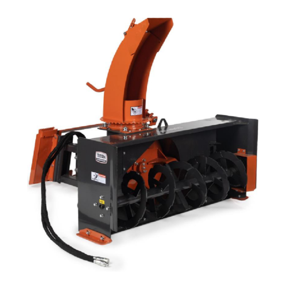
- Page 8 PACKING LIST AND ASSEMBLY INSTRUCTIONS PACKING DESCRIPTION a. Remove the packing, check goods are without defect and omission. FIGURE 1: Your New Snowblower as It Is Shipped To You...
- Page 9 FIGURE 2: Packaging frame decomposition PACKING RACK LIST:...
-
Page 10: Packing List
1.2 PACKING LIST FIGURE 3: The Snowblower and Accessory in Package The detailed packing list as the following Table 1. TABLE 1: Packing List NOTE: PAY ATTENTION TO THE MOTOR STEERING. - Page 11 The detailed description of Handle & Rear Bracket and Screw Rod Assembly FIGURE 4: Handle & Rear Bracket and Screw Rod Assembly The detailed description of Discharge Chute Assembly & Snow Spray Mask Assembly and Fittings FIGURE 5: Discharge Chute Assembly, Snow Spray Mask Assembly & fittings...
-
Page 12: Installation Wizard
INSTALLATION WIZARD The installation wizard will guide you to finish the final assembly of your new Snow Blower. TOOLS REQUIRED 1/2” Ratchet Wrench with 10mm, 14mm, 17mm and19mm sleeves • 8-10, 12-14, 17-19 Spanner • TORQUE APPLICATION INSTALLATION STEP 1: Installing Discharge Chute Assembly, Snow Spray Mask Assembly, and Fittings 1 FIGURE 6: Discharge Chute Assembly, Snow Spray Mask Assembly, and Fittings 1 a. - Page 13 FIGURE 7: Discharge Chute Assembly, Snow Spray Mask Assembly, and Fittings 2 NOTE: The support ring must be located in the roller groove. STEP 2: Installing Handle, Rear bracket & Screw rod assembly a. Locate the front bracket on the position shown in the Figure8, and then fix it with M10x25 bolt, plain washer 10 and spring washer 10.
- Page 14 FIGURE 9: Rear bracket installation location c. Insert the pin shaft into the hole of the front bracket, put the washer 28 into the inner side, and then fix the Screw rod weldment with the pin shaft with the M6x45 bolt and locknut M6.
- Page 15 FIGURE 11: Handle installation Note: Pay attention to the meshing of welding parts and gear disc. WARNING: SAE EP 90W Gear oil must be filled before you finish the final assembly and start your first use. Overfilling or underfilling gear oil may cause gearbox seizing or damage.
- Page 16 BOLT TORQUE The tables shown below give correct torque values for various bolts and cap screws. Tighten all bolts to the torques specified unless otherwise noted. Check tightness of bolts periodically, using bolt torque chart as a guide. Replace hardware with the same strength bolt. Torque figures indicated above are valid for non-greased or non-oiled threads and heads otherwise specified.
-
Page 17: Maintenance And Storage
MAINTENANCE AND STORAGE... - Page 18 SSBP SERIES SKID STEER SNOW BLOWER PART LIST...
- Page 24 CAUTION: The snow blowers might be slightly different between different production time.
- Page 25 ACKNOWLEDGEMENT OF RISK AND RELEASE OF LIABILITY The use of any equipment, including this one, involves the potential risk of injury. Apart from any warranty claim that might be presented for a claimed defect in material or workmanship of the product, you accept and assume full responsibility for any and all injuries, damages (both economic and non- economic), and losses of any type, which may occur, and you fully and forever release and discharge Titan, its insurers, employees, officers, directors, associates, and agents from any and all claims,...
- Page 26 NEED HELP? CONTACT US FIRST. 1-800-605-7595 info@palletworks.com www.palletforks.com © 2021 Titan Brands...
Need help?
Do you have a question about the SSBP150 and is the answer not in the manual?
Questions and answers