Table of Contents
Advertisement
Quick Links
SOLO GA1
USER'S MANUAL
Rev. 2.0 - April 2022
For support, contact us at
support@virtual-fly.com
© 2022 Virtual Fly, SL
All trademarks and brand names are
trademarks or registered trademarks of their
respective owners. All rights reserved.
C. Maria Aurèlia Capmany, 21
P.I. La Fàbrica – 08297 Castellgalí (Spain)
Phone: (+34) 938 333 301
https://www.virtual-fly.com
Advertisement
Table of Contents

Related Manuals for Virtualfly SOLO GA1


Summary of Contents for Virtualfly SOLO GA1
- Page 1 SOLO GA1 USER’S MANUAL Rev. 2.0 - April 2022 For support, contact us at support@virtual-fly.com © 2022 Virtual Fly, SL C. Maria Aurèlia Capmany, 21 All trademarks and brand names are P.I. La Fàbrica – 08297 Castellgalí (Spain) trademarks or registered trademarks of their Phone: (+34) 938 333 301 respective owners.
-
Page 2: Table Of Contents
2.1 CONNECTING TO PC..........4 2.2 ADJUSTING MAGNETIC LABELS ACCCORDING TO AIRCRAFT TYPE......5 2.3 G1000 BACKLIGHT CONTROLS......6 2.4 G1000 OSD CONTROLS........6 2.5 SOLO GA1 NAKED EDITION.........7 3. SOFTWARE SETUP 3.1 CONFIGURING PFD/MFD DISPLAYS IN WINDOWS................9 3.2 INTERFACE WITH FLIGHT SIMULATION SOFTWARE AND PC...........10 3.3 CONFIGURING G1000 SCREENS INSIDE... -
Page 3: In The Box
D) Power supply 12v (Not included in "Naked Edition") E) Power strip F) HDMI cables (Not included in "Naked Edition") G) Magnetic Labels H) Spiral cable wrap I) Cable ties J) Quick Start Guide K) Registration Key SOLO GA1 | User’s manual... -
Page 4: Connecting To Pc
USB (C) USB (C) USB Hub (B) The SOLO GA1 has been developed to be pluggable to any standard Windows computer that has two free video outputs and one free USB port. Most of the connections of your SOLO GA1 will come assembled so you have to connect the least amount of cables. -
Page 5: Adjusting Magnetic Labels
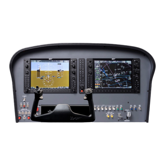
2.2 ADJUSTING MAGNETIC LABELS SOLO GA1 panel in their correct location, as displayed in ACCORDING TO AIRCRAFT TYPE the image below. The image depicts the SOLO GA1 with the turboprop magnetic labels applied. The SOLO GA1 is a multifuncion panel and some switches change their function depending on whether the selected aircraft is a piston, turbo-prop. -
Page 6: G1000 Backlight Controls
Rotate whilst you press the “PILOT PASS” (d) to adjust the • EXIT: push “VOL SQ” (e) + move JOYSTICK “RANGE” (f) backlighting of the Audio panel. left. • POWER: push “VOL SQ” (e) + push “ENT” (g). SOLO GA1 | User’s manual... -
Page 7: Solo Ga1 Naked Edition
G) HDMI cables (x2) D) EU Power cable H) USB cable (x2) Mount the PFD/MFD panels to the SOLO GA1 Naked from the E) US Power cable I) M4x16 Countersunk screws front with the provided countersunk screws (I) from the VF- (x8) and "U"... - Page 8 After mounting the PFD, MFD and Audio panels, you must connect these to the SOLO GA1 Naked and flight simulation PC. The cables described below are provided with the VF- G1000 package. You must connect: • The jack cables (F) from the Audio panel to PFD and MFD panels, as displayed in the following diagram.
-
Page 9: Software Setup
We recommend to set up the MFD on the right-hand- side of the PFD panel. On “Display Settings”, the PFD and SOLO GA1 panel includes a VF-G1000 system with a Primary MFD displays must be positioned under the main display, as flight display (PFD), Audio Panel and Multi flight display (MFD). -
Page 10: Interface With Flight Simulation Software And Pc
Virtual Fly flight controls. VFHub takes care of making your SOLO GA1 work with MSFS You can download the latest VFHub version from this link: and X-Plane 11, so it must always be running when you use https://www.virtual-fly.com/setup-support. -
Page 11: Configuring G1000 Screens Inside Simulation Software
Make sure your SOLO GA1 is connected to your computer. 3.3 CONFIGURING G1000 SCREENS INSIDE Run VFHub, and verify that the VF-G1000 status displayed in SIMULATION SOFTWARE the Dashboard is “Connected”: MSFS After starting a flight with a G1000 airplane, click on both PFD and MFD screens in the virtual cockpit while you press the “ALT GR”... - Page 12 You will see the top windows frame from the dragged PFD and MFD screens at the bottom of your main display as displayed below, but don’t worry, once you finish configuring it, it won’t be visible. SOLO GA1 | User’s manual...
- Page 13 5. Repeat the process for the MFD screen. 6. When both windows are properly adjusted to the VF-G1000 displays, click on your main display and the top frame from the PFD and MFD G1000 pop-out windows will be hidden. SOLO GA1 | User’s manual...
-
Page 14: Engine Starting Procedures
Never use these procedures for pilot training or for real aviation. The diagram below shows the position of every switch in the SOLO GA1 along with the step that corresponds to their 4.1 START & STOP FOR PISTON ENGINES application when starting the piston engine. - Page 15 5. Switch off the MAGNETO switch(es). 6. Switch off the BAT switch. The diagram below shows the position of every switch in the SOLO GA1 along with the step that corresponds to their application when stopping the piston engine. SOLO GA1 | User’s manual...
-
Page 16: Start & Stop Turboprop Engines
The diagram below shows the position of every switch in 2. Move the MIXTURE lever to RICH position. the SOLO GA1 along with the step that corresponds to their 3. Move the PROP RPM lever to HIGH position. application when starting the turboprop engine. - Page 17 4. Switch off the GEN switch(es). for starting and stopping the engines. 5. Switch off the BAT switch. The diagram below shows the position of every switch in the SOLO GA1 along with the step that corresponds to their SOLO GA1 | User’s manual...
-
Page 18: Troubleshooting
PFD/MFD do not interact with buttons simultaneously in the device. simulation software. Make sure SOLO GA1, PFD and MFD receives 12v PFD and MFD are not detected by power. Also check in the Flight simulation computer your flight simulator computer. -
Page 19: Remote Support
In case you need help from Virtual Fly's technical team, there is the possibility to schedule a remote connection to your flight simulation computer and SOLO GA1. For that, you should: 1. Ensure your flight simulator computer is connected to the internet. -
Page 20: Technical Specifications
7. TECHNICAL SPECIFICATIONS Power Supply: 100-240 VAC, mono, 50-60 Hz Nominal intensity: 0,75 A Weight: 15 kg Height: 43,5 cm Depth: 21,5 cm Width: 80 cm Compatibility: MSFS and X-Plane 11 SOLO GA1 | User’s manual... -
Page 21: Hardware Setup 8. Aircraft Compatibility
8. AIRCRAFT COMPATIBILITY The SOLO GA1 is compatible with the following aircraft in MSFS and X-Plane 11: MSFS X-Plane 11 Cessna Skyhawk (G1000) Cirrus SR22 Beechcraft Baron 58 Diamond Aircraft DA40NG (G1000) - Free MOD from X-Plane Forums Any plane fitted with default...
Need help?
Do you have a question about the SOLO GA1 and is the answer not in the manual?
Questions and answers