Table of Contents
Advertisement
Quick Links
Stocked in:
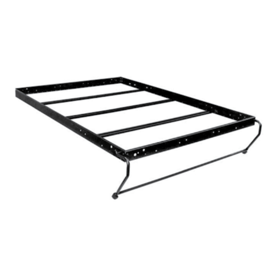
One universal bed frame for each of Single, Double, or Queen wall beds.
May be mounted in either vertical or horizontal modes.
A lightweight, universal, structural steel bed frame with double overlap steel stiffeners,
completed with fold-away leg system. Designed to exceed the strength of wood or
aluminum as well as residential and commercial specifications.
Architectural Products by Outwater assumes no liability for improper installation.
architectural products
ASSEMBLY INSTRUCTIONS
MODEL #SBF: STEEL BED FRAME
° Single/Twin
° Double/Full
° Queen
Designed to Exceed International ISO 9002
Standards for residential specifications
***15 YEAR WARRANTY ***
OUTWATER
by
L.L.C.
° Single/Twin X-Long
° Double/Full X-Long
° King
Page 1
Advertisement
Table of Contents

Related Manuals for Outwater architectural products alpha bed SBF

Summary of Contents for Outwater architectural products alpha bed SBF
- Page 1 Designed to exceed the strength of wood or aluminum as well as residential and commercial specifications. Designed to Exceed International ISO 9002 Standards for residential specifications ***15 YEAR WARRANTY *** Architectural Products by Outwater assumes no liability for improper installation. Page 1...
-
Page 2: Project Start-Up
5. Attach Bed Cabinet to wall. 6. Assemble Steel Bed Frame to Bed Face Panels. 7. Install the Bed Face Panel in Cabinet. 8. Install Handles, Left Assembly, Mechanism Covers, Mattress Architectural Products by Outwater assumes no liability for improper installation. Page 2... - Page 3 Allen Head Bolt 5/16-18 x 1” Position Mechanism Arm on Frame Side Section Hex Head Nylock Nut Secure Bolts and Screws Allen Wrench 5/16” For Allen Head Bolts Architectural Products by Outwater assumes no liability for improper installation. Page 3...
-
Page 4: Component Layout
Frame has mounting holes to use any of 4 Power Packs: SBLM, SBLM-A, ACBM, GPLS Frame laid out for assembly in the vertical orientation. Frame laid out for assembly in the horizontal orientation. Architectural Products by Outwater assumes no liability for improper installation. Page 4... - Page 5 Bottom Rear Base 6” (152) 64” (1626) 2 Long Edges Bottom Kick with 13” (330mm) Leg 4” (102) 64” (1626) 2 Long Edges or Top Facia with 11” (279mm) Leg Architectural Products by Outwater assumes no liability for improper installation. Page 5...
- Page 6 *RECOMMENDED STIFFENER PLACEMENT FOR KING BEDS* Use 5-stiffeners total: 3 - equally spaced head to foot 2 - against inside of End Rail (foot end) to provide added strength. Architectural Products by Outwater assumes no liability for improper installation. Page 6...
- Page 7 Max Mattress Size 39” x 75” (990 x 1905) 54” x 75” (1372 x 1905) 60” x 80” (1524 x 2032) Max Mattress Thickness 12” (305) 12” (305) 12” (305) Architectural Products by Outwater assumes no liability for improper installation. Page 7...
- Page 8 (8 x 32mm) Machine Screws. 4. Mount the Lift Mechanisms. NOTE: All location measurements are from the front edge of the Cabinet Side Panels. Refer to Drawings 3 & 4. Architectural Products by Outwater assumes no liability for improper installation. Page 8...
-
Page 9: Spring Application Chart
You should have an equal number of springs on each side of the center hole. Use the same number of springs and the same layout on both the left and right mechanisms. Architectural Products by Outwater assumes no liability for improper installation. Page 9... - Page 10 Side Panels and 1-1/4” (32mm) down from the top of the Side Panels so it is flush with the bottom edge of the Top Facia. The Top Facia will cover the front edge of the Top Panel. Architectural Products by Outwater assumes no liability for improper installation. Page 10...
- Page 11 Bottom Kick and the 4” (102) board as the Top Facia. When using the 13” (330) Beg Leg Assembly, use the 4” (102) tall board as the Bottom Kick and the 2” (51) board as the Top Facia. Architectural Products by Outwater assumes no liability for improper installation. Page 11...
-
Page 12: Step 4: Attach Bed Cabinet Securely To Wall
Panel with #8 x 3/4” (M4 x 19mm) wood screws. Attach warning label to top of cabinet. Attach three Bumper Buttons to bottom of the front edge of the Top Facia. These Bumpers allow the Bed Face Panel to close quietly. Architectural Products by Outwater assumes no liability for improper installation. Page 12... -
Page 13: Step 5: Assemble Steel Bed Frame To Face Panels
STEP 5: ASSEMBLE STEEL BED FRAME TO FACE PANELS Architectural Products by Outwater assumes no liability for improper installation. Page 13... - Page 14 If possible have a helper assist in the setting of the mechanism and loading of the bed face panel. DO NOT reach behind the tension arm when you are doing the setting procedure. Architectural Products by Outwater assumes no liability for improper installation. Page 14...
- Page 15 Leveling of the bed cabinet is essential. Check the level both side to side and front to back. Proper leveling will facilitate proper closure and exact sight lines of the fit of the Face Panel to the Cabinet. Architectural Products by Outwater assumes no liability for improper installation. Page 15...
-
Page 16: Step 8: Install Handles - Legs - Mechanism Covers - Mattress
5. Snap the powder coated steel mechanism covers in place - secure with #8 x 1-1/4” (M4 x 32mm) black wood screws through the standoff on the backer plate. Architectural Products by Outwater assumes no liability for improper installation. Page 16... - Page 17 Bed Face Panel and add or subtract springs. At this time, you may decide to use one more or less spring(s) on the left or right side Lift Mechanism. Architectural Products by Outwater assumes no liability for improper installation. Page 17...
- Page 18 (18 x 76mm) wood stiffener held in place with wood screws to the face panels. Use the steel stiffeners as well; one next to the wood stiffener and the other two equally spaced. Architectural Products by Outwater assumes no liability for improper installation. Page 18...
Need help?
Do you have a question about the architectural products alpha bed SBF and is the answer not in the manual?
Questions and answers