
Summary of Contents for Astraada SRV-64
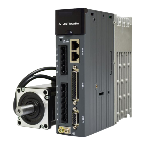
- Page 1 Operation Manual Astraada SRV-64 AC Servo drives The owner of Astraada brand is ASTOR Sp. z o.o.
- Page 2 Preface Preface Thanks for choosing Astraada AS64 series AC servo drive (AS64 drive for short). Using the modular structure, AS64 drive provides abundant functions and achieves excellent performance. The upper computer software uses USB communication, and the available control bus options include Modbus, CANopen, and EtherCAT.
-
Page 3: Safety Precautions
AS64 series AC servo drive Safety precautions Safety precautions Safety symbols Read this manual and follow the instructions. Do not touch terminals within 15 minutes after power-on or power-off. Otherwise, electric shock may result. Do not touch the heat sink. Otherwise, burns may result. The contact current can reach 0.5mA. - Page 4 AS64 series AC servo drive Safety precautions ⚫ Rewire the drive at least 15 minutes after disconnecting it from the power supply. Otherwise, electric shock may result. ⚫ Use proper grounding techniques because the touch current may reach 0.5mA. Otherwise, electric shock may result.
-
Page 5: Table Of Contents
AS64 series AC servo drive Contents Contents Preface ............................. Safety precautions ......................... II Contents ............................IV 1 Overview ............................. 1 1.1 Servo drive ..........................2 1.2 Servo motor ..........................8 1.3 Cables ............................9 1.4 Brake resistor specifications ..................... 11 2 Installation instructions ...................... - Page 6 AS64 series AC servo drive Contents 6.4 I/O management (group P3) ....................128 6.5 Extension and application (group P4) ..................146 6.6 Program Jog, homing, and PTP control (group P5) ..............165 6.7 Application functions (group P6) ..................... 179 6.8 PTP control (groups PtP0, PtP1, and PtP2) ................185 6.9 Status monitoring ........................
-
Page 7: Overview
AS64 series AC servo drive Overview Overview 1.1 Servo drive ..........................2 1.1.1 Drive introduction ..................... 2 1.1.2 Outline drawing ......................6 1.1.3 Drive naming ......................7 1.1.4 Drive nameplate ....................... 8 1.1.5 Drive ratings and frame sizes..................8 1.2 Servo motor ..........................8 1.2.1 Motor nameplate ...................... -
Page 8: Servo Drive
AS64 series AC servo drive Overview 1.1 Servo drive 1.1.1 Drive introduction AS64 series servo drive (100W–2kW) Specification Description Power 220V system input 1PH/3PH, AC 220V (±15%),47Hz–63Hz supply voltage 8 inputs for the standard, pulse, and CANopen bus types; Input 7 inputs for the EtherCAT bus type (The function is Control configurable through parameter settings.) - Page 9 AS64 series AC servo drive Overview AS64 series servo drive (100W–2kW) Specification Description 3: Switching electronic gear ratios 4: Switching vibration control Control Such as positioning completion output output Max. pulse Photoelectric coupling: differential input of input 4Mpps or open collector input of 200kpps frequency 1: Pulse + direction Pulse input...
- Page 10 AS64 series AC servo drive Overview AS64 series servo drive (100W–2kW) Specification Description Internal The internal eight-step speeds can be switched based on speed external control inputs. command Speed command This supports both independent ACC/DEC time setting ACC/DEC and S-curve ACC/DEC setting. adjustment Zero speed In speed mode, this allows the hybrid speed or position...
- Page 11 AS64 series AC servo drive Overview AS64 series servo drive (100W–2kW) Specification Description 1: Position 2: Speed 3: ACC time Route 4: DEC time setting 5: Stop timer 6: Status output 7: Running mode 1: LS signal 2: Phase-Z signal Homing 3: LS signal + phase-Z signal 4: Torque limit signal...
-
Page 12: Outline Drawing
AS64 series AC servo drive Overview 1.1.2 Outline drawing For standard model CN 5 : F u lly-clo sed lo op LE D disp la y Ope ratio n pa ne l CN 4 : U p pe r co mp ut er Ch arg e in dica to r CN 3 : C A N /R S4 85 co m mu n ica tio n Ma in-circuit po w er... -
Page 13: Drive Naming
AS64 series AC servo drive Overview 1.1.3 Drive naming Description Example ① Product series AS64: AS64 series SRV: servo drive ② Product category 2: 1 x 220VAC ③ Input voltage class 4: 3 x 400VAC 0C2: 200W 0C4: 400W 0C7: 750W ④... -
Page 14: Servo Motor
AS64 series AC servo drive Overview 1.1.4 Drive nameplate 1.1.5 Drive ratings and frame sizes Input Output Frame Model Rated Rated size Voltage (V) Power (kW) current (A) current (A) AS64SRV20C2-S 1PH/3PH 220 1.8/0.8 AS64SRV20C4-S 1PH/3PH 220 3.6/1.5 AS64SRV20C7-S 1PH/3PH 220 6.8/2.8 0.75 AS64SRV21C0-S... -
Page 15: Cables
AS64 series AC servo drive Overview 5.2.1 "Display". Incorrect setting may cause abnormal running of the servo system or even a major fault to the drive and motor. 1.2.2 Motor naming Description Example ① Product series AS64: AS64 series MT: servo motor ②... -
Page 16: Power Cable Naming
AS64 series AC servo drive Overview 1.3.2 Power cable naming Description Example AS64: AS64 series Product series ① CB: servo motor ② Product category ③ Cable type L: Power cable 2: 1 x 220VAC ④ Voltage class 4: 3 x 400VAC 0C7: up to 750W ⑤... -
Page 17: Brake Resistor Specifications
AS64 series AC servo drive Overview Description Example L15: 15 meters L20: 20 meters I: incremental ⑦ Encoder type A: absolute 1.3.4 Encoder cable with battery box naming Description Example AS64: AS64 series ① Product series CB: servo motor ② Product category ③... -
Page 18: Installation Instructions
AS64 series AC servo drive Installation instructions Installation instructions 2.1 Drive dimensions ........................13 2.1.1 Dimension drawing for frame size A/B ..............13 2.1.2 Dimension drawing for frame size C ............... 13 2.1.3 Models and dimensions ..................14 2.2 Drive installing ......................... 14 2.2.1 Installation mode .................... -
Page 19: Drive Dimensions
AS64 series AC servo drive Installation instructions 2.1 Drive dimensions 2.1.1 Dimension drawing for frame size A/B 2.1.2 Dimension drawing for frame size C -13-... -
Page 20: Drive Installing
AS64 series AC servo drive Installation instructions 2.1.3 Models and dimensions Mount Outline dimensions dimensions Mount hole Frame size Model (mm) (mm) (mm) (mm) (mm) (mm) AS64SRV20C2-S M4(Φ5) AS64SRV20C4-S AS64SRV20C7-S M4(Φ5) AS64SRV21C0-S AS64SRV21C5-S M4(Φ5) AS64SRV22C0-S 2.2 Drive installing 2.2.1 Installation mode Base installation mode There is a Φ5 installation hole at the lower left corner and one at the upper right corner of the rear panel. -
Page 21: Installation Directions And Clearances
AS64 series AC servo drive Installation instructions 2.2.2 Installation directions and clearances Install the servo drive vertically and keep enough space for good ventilation. If necessary, install a fan to ensure the temperature inside the control cabinet is lower than 45°C. Installing one drive >... -
Page 22: Motor Outline And Mounting Dimensions
AS64 series AC servo drive Installation instructions 2.3 Motor outline and mounting dimensions Note: Motor structural dimensions may vary with design modification. If you are sensitive to motor mounting dimensions, check the dimensions with sales staff before ordering. In this section, if not otherwise specified, all the dimensions are expressed in millimeterm). -
Page 23: Motor Installing
AS64 series AC servo drive Installation instructions 2.3.3 For base-130 motors (h9) -0.03 18.5 ¦ µ 2 2 (h6) -0.013 ¦ µ 1 65 (Equally spaced) ¦ µ 9 Through-hole ¦ µ 1 45 ¦ µ 2 4.4 L (mm) Motor model With permanent magnet (with multiturn absolute encoder) - Page 24 AS64 series AC servo drive Installation instructions Class F (155°C) Insulation class IP65 IP rating Application Temperature: -20°C–+40°C (non-frozen); RH: below 90% (no condensation) environment -18-...
-
Page 25: Wiring Instructions
AS64 series AC servo drive Wiring instructions Wiring instructions 3.1 System wiring .......................... 20 3.1.1 Input power cable requirements ................21 3.1.2 Control power cable requirements ................21 3.1.3 Main circuit cable diameters ................... 22 3.1.4 EMI filter models ..................... 22 3.2 Main circuit terminal wiring ....................... -
Page 26: System Wiring
AS64 series AC servo drive Wiring instructions 3.1 System wiring Po w e r Bre a ke r T o c u t o ff th e c ir c u it if p ow e r c a bl e o v e r c u rr en t oc c u rs . -
Page 27: Input Power Cable Requirements
AS64 series AC servo drive Wiring instructions 3.1.1 Input power cable requirements The input power cable dimensions must comply with local regulations. The input power cable must be able to withstand the load current. ⚫ The maximum rated temperature margin of the input power cable cannot be lower than 70°C ⚫... -
Page 28: Main Circuit Cable Diameters
AS64 series AC servo drive Wiring instructions 3.1.3 Main circuit cable diameters Main circuit cable diameters for models in the small power range (200W–2kW) Recommended cable Connectable cable diameter (mm diameter (mm Terminal Tightening screw torque L1\L2\ L1\L2\ Drive model L1C\ (+),B2 size... -
Page 29: Main Circuit Terminal Wiring
AS64 series AC servo drive Wiring instructions 3.2 Main circuit terminal wiring 3.2.1 Single-phase 220V wiring diagram · Employ this emergency stop circuit. · Add a surge absorber to each end of the electromagnetic contactor coil. · Input voltage of power: Breaker AC220V(±15%) Filter... -
Page 30: Three-Phase 220V Wiring Diagram
AS64 series AC servo drive Wiring instructions 3.2.2 Three-phase 220V wiring diagram · Employ this emergency stop circuit. · Add a surge absorber to each end of the electromagnetic contactor coil. · Input voltage of power: Breaker AC 220V(±15%) filter ·... -
Page 31: Motor Power Cable Wiring
AS64 series AC servo drive Wiring instructions 3.3 Motor power cable wiring 3.3.1 Power cable for incremental base 40/60/80 motors View in direction A Wiring mapping Definition Core wire color X1.1 X2.2 Blue X1.2 X2.1 X1.3 X2.3 Brown Ground terminal X2.4 Yellow/Green + shield 3.3.2 Power cable for absolute base 40/60/80 motors... -
Page 32: Wiring For Control I/O Terminal Cn1
AS64 series AC servo drive Wiring instructions 3.4 Wiring for control I/O terminal CN1 DO2+ DO1+ DO6+ DO3+ DO5+ DO3- DO1- COM+ DO6- DO4+ DO5- PULS- PULS+ CLR+ DO2- CLR- DO4- SIGN- SIGN+ CN1 plug pin and signal layout Note: This is the interface definition for the standard model. For details about the terminal functions and applications, see chapter 4 "Control modes". -
Page 33: Absolute Base 40/60/80 Encoder Cable
AS64 series AC servo drive Wiring instructions Wiring mapping Core wire Signal Core wire color structure X1.8 X2.8 Yellow/Black X1.3 X2.3 Twisted X1.4 X2.4 Red/White X1.6 X2.6 Orange Twisted X1.11 X2.11 Orange/Black X1.9 X2.9 Blue Twisted X1.10 X2.10 Blue/Black X1.13 X2.13 Green Twisted... -
Page 34: Wiring For Rs485/Can Terminal Cn3
AS64 series AC servo drive Wiring instructions Wiring mapping Core wire Signal Core wire color structure X1.7 X2.14 Black/White X1.2 X2.12 Yellow Twisted X1.8 X2.15 Yellow/Black X1.3 X2.7 Twisted X1.4 X2.4 Red/White X1.6 X2.10 Orange Twisted X1.11 X2.13 Orange/Black X1.9 X2.8 Blue Twisted... -
Page 35: Wiring For Usb Terminal Cn4
AS64 series AC servo drive Wiring instructions CN3 functions Name Function Remarks GND_CAN Power ground for CAN chip The same interface is GND_485 Power ground for RS485 chip provided for RS485 and RS485+ RS485 data + communication. RS485- RS485 data - Each signal occupies two CAN_L CAN data -... -
Page 36: Wiring For Sto Terminal Cn11
AS64 series AC servo drive Wiring instructions Name Function Remarks Parallel encoder signal V-/Encoder serial EXV-/EXB_SD- data + EXW- Parallel encoder signal W- EXB- Parallel (or second) encoder signal B- EXB+ Parallel (or second) encoder signal B+ EXU- Parallel encoder signal U- Power ground, connecting to the internal EX0V EXZ-... -
Page 37: Control Modes
AS64 series AC servo drive Control modes Control modes 4.1 Standard wiring diagram for position control ................32 4.2 Standard wiring diagram for speed control ................33 4.3 Standard wiring diagram for torque control ................34 4.4 Function description for CN1 ....................35 4.4.1 CN1 terminal pins .................... -
Page 38: Standard Wiring Diagram For Position Control
AS64 series AC servo drive Control modes 4.1 Standard wiring diagram for position control -32-... -
Page 39: Standard Wiring Diagram For Speed Control
AS64 series AC servo drive Control modes 4.2 Standard wiring diagram for speed control -33-... -
Page 40: Standard Wiring Diagram For Torque Control
AS64 series AC servo drive Control modes 4.3 Standard wiring diagram for torque control -34-... -
Page 41: Function Description For Cn1
AS64 series AC servo drive Control modes 4.4 Function description for CN1 4.4.1 CN1 terminal pins DO2+ DO1+ DO6+ DO3+ DO5+ DO3- DO1- COM+ DO6- DO4+ DO5- PULS- PULS+ CLR+ DO2- CLR- DO4- SIGN- SIGN+ CN1 plug pin and signal layout 4.4.2 CN1 pin functions Sign Function... -
Page 42: Power Signals
AS64 series AC servo drive Control modes 4.4.3 Power signals Sign Name Function Ground for analog input and output signals and A/B/Z Signal ground frequency dividing signals ⚫ If DI is active low (0V), COM+ connects to the positive polarity of the external 12V–24V power. DI common COM+ ⚫... - Page 43 AS64 series AC servo drive Control modes Position mode Speed mode Sign Name Default Symbol Function Default Symbol Function Digital output DO2 15/19 0x003 Fault output 0x003 Fault output Digital output Position Speed 11/8 0x007 0x009 COIN completion consistency Digital output Zero-speed Zero-speed DO4 29/35...
- Page 44 AS64 series AC servo drive Control modes Applicable Signal Symbol Function mode Signal of disabling the drive to the forward or reverse direction. The detailed action is associated with the setting of P3.40 [Disable travel limit switch]. If P3.40 is set to 0: ⚫...
- Page 45 AS64 series AC servo drive Control modes Applicable Signal Symbol Function mode Clearing residual pulses 0x07 Control signal of clearing residual pulses. The detailed action is associated with the setting of P3.45 [Residual pulse clearing mode]. If P3.45 is set to 0, which indicates electrical-level clearing, residual pulses are always 0 when this digital input is valid.
- Page 46 AS64 series AC servo drive Control modes Signals of selecting from internal-speed commands 1 to 8 or from internal speed limits 1 to 4. Associated parameter Control mode Setting of P0.40 SPD3 SPD2 SPD1 and setting P0.46, internal speed 1 P0.47, internal speed 2 P0.48, internal speed 3 P0.49, internal speed 4...
- Page 47 AS64 series AC servo drive Control modes Internal position command 5 POS5 0x20 Internal position command 6 POS6 0x21 Internal position command 7 POS7 0x22 These signals are used to select from position commands 0–127 in point-to-point (PTP) control mode, with the same function as P5.20 [PTP trigger signal] in bus control mode. They are valid only when P0.20 [Position command source] is set to 2.
- Page 48 AS64 series AC servo drive Control modes PtP2.55[Position of segment 127] Applicable Signal Symbol Function mode External fault 0x14 Signal of reporting an external fault alarm. If this digital input is valid, the drive reports the alarm Er10-3 and stops. Applicable Signal Symbol...
- Page 49 AS64 series AC servo drive Control modes Applicable Signal Symbol Function mode Numerator selection 1 for 0x19 electronic gear ratio Numerator selection 2 for 0x1A electronic gear ratio This group of signal is used to switch between a maximum of four electronic gear ratios. Before using this function group, set P0.22 [Pulses per motor resolution] to 0 and then set numerators (P0.25–P0.29).
- Page 50 AS64 series AC servo drive Control modes Signal of externally controlling quick stop. If this digital input is valid, the control motor of the drive decelerates from current speed to 0 according to the regular curve set by P0.69 [DEC time for quick stop]. If it changes from valid to invalid, the motor restores to the state prior to quick stop.
- Page 51 AS64 series AC servo drive Control modes Applicable Signal Symbol Function mode Gantry synchronization 0x2D cancellation input If this digital input is valid, gantry synchronization is cancelled. Applicable Signal Symbol Function mode Master gantry synchronization 0x2E alignment sensor Signal used by the master gantry synchronization alignment sensor. Applicable Signal Symbol...
- Page 52 AS64 series AC servo drive Control modes Applicable Signal Symbol Function mode Magnetic pole check PDET 0x34 If this digital input is valid, the magnetic pole is checked. 4.4.4.2 Digital output functions Applicable Signal Symbol Function mode Servo readiness output 0x01 This signal indicates that the drive is ready.
- Page 53 AS64 series AC servo drive Control modes Applicable Signal Symbol Function mode Positioning completion 0x07 This signal outputs positioning is completed. If it is valid, the positioning is completed. Applicable Signal Symbol Function mode Control mode switching status MCHS 0x08 This signal indicates the switching between different control modes.
- Page 54 AS64 series AC servo drive Control modes Applicable Signal Symbol Function mode Zero-speed output 0x0D This signal outputs whether the current speed feedback is zero. Applicable Signal Symbol Function mode Torque being limited 0x0E This signal outputs the torque is being limited. If it is valid, the current torque output reaches the maximum torque limit.
-
Page 55: Pulse Input Signals And Functions
AS64 series AC servo drive Control modes Applicable Signal Symbol Function mode PTP output 3 PTPO3 0x19 It is the signal of PTP output 3. Applicable Signal Symbol Function mode PTP output 4 PTPO4 0x1A It is the signal of PTP output 4. Applicable Signal Symbol... -
Page 56: Analog Input Signals And Functions
AS64 series AC servo drive Control modes Sign Signal Function PULS+ Position command ⚫ In position control mode, the terminals function as position command input terminals. pulse input 1 PULS- ⚫ In other control modes, the terminals are invalid. Position command ⚫... -
Page 57: Wiring Description For Cn1
AS64 series AC servo drive Control modes 4.5 Wiring description for CN1 4.5.1 Digital input circuit wiring DC12~24V DC12~24V 2 COM+ 2 COM+ 16 DI1 16 DI1 Drive side Drive side DC12~24V DC12~24V 2 COM+ 2 COM+ 16 DI1 16 DI1 Drive side Drive side Active low... - Page 58 AS64 series AC servo drive Control modes Shielded Twisted cable pair 38 OCP PULS 24 PULS- 31 OCS SIGN 33 SIGN- 36 OCC 18 CLR- DC24V Control module Drive side side Control module using PNP triodes with common anode: DC24V Shielded Twisted cable...
- Page 59 AS64 series AC servo drive Control modes Shielded Twisted cable pair 23 PULS+ PULS Current limit resistor R 24 PULS- 32 SIGN+ SIGN Current limit resistor R 33 SIGN- 22 CLR+ Current limit resistor R 18 CLR- DC12~24V Control module Drive side side Control module using PNP triodes with common anode:...
-
Page 60: Analog Input Circuit Wiring
AS64 series AC servo drive Control modes 4.5.3 Analog input circuit wiring 20 AD1 6 GND Twisted pair 7 AD2 6 GND Connect the shielded cable according to device requirements Control Drive side module side In the two analog input circuits: AD1 is accurate to 16 bits (optional, applicable only to standard models) and AD2 is accurate to 12 bits (preconfigured for standard models);... -
Page 61: Frequency-Division Output Circuit Wiring Of Encoder Feedback Signals
AS64 series AC servo drive Control modes 4.5.5 Frequency-division output circuit wiring of encoder feedback signals Differential method: AM26LS32 Shielded Twisted Terminal or equivalent chip cable pair resistor OA+ 44 OB+ 41 OZ+ 28 GND 6 Connect the shielded cable according to Drive side device requirements ⚫... -
Page 62: Wiring Description For Cn5
AS64 series AC servo drive Control modes Note: The brake winding must use independent 24V power and cannot share the control power or relay coil power. Emergency-stop Motor button DC24V Surge BRK+ power absorber Brake special for winding Fuse (5A) brake BRK- 26 winding... -
Page 63: Wiring Description For Cn11
AS64 series AC servo drive Control modes 4.7 Wiring description for CN11 Wiring for the safety terminal circuit ① Safety output signals are ① Safety terminal signals are active high active high EDM+ HWBB1+ 3 HWBB1- 4 EDM- HWBB2+ 5 HWBB2- 6 ②Safety terminal signals ②Safety output signals... -
Page 64: Operating And Running
AS64 series AC servo drive Operating and running Operating and running 5.1 Running ........................... 59 5.1.1 First power-on ......................59 5.1.2 Trial run by jogging ....................60 5.1.3 Running in position control mode ................61 5.1.4 Running in speed control mode ................62 5.1.5 Running in the torque control mode ................ -
Page 65: Running
AS64 series AC servo drive Operating and running 5.1 Running 5.1.1 First power-on Ensure the following before the power-on: Wiring ⚫ The power supply (namely, cables L1, L2, L3, L1C, and L2C or cables R, S, and T) of the servo drive is connected correctly. -
Page 66: Trial Run By Jogging
AS64 series AC servo drive Operating and running For the models in the medium power range (7.5kW–55kW), you only need to connect the main circuit three-phase power (namely, terminals R, S, and T). 5.1.1.2 Checking after power-on After both the control circuit and main circuit power supplies are switched on: If the powering is normal, each position on the LED panel displays 0 and then 8. -
Page 67: Running In Position Control Mode
AS64 series AC servo drive Operating and running 5.1.3 Running in position control mode Simplified wiring Servo drive 12~24V COM+ … Parameter Function Setting … … P0.03 Control mode … … Pulses per motor Depends on the … P0.22 resolution actual situation. -
Page 68: Running In Speed Control Mode
AS64 series AC servo drive Operating and running 5.1.4 Running in speed control mode Simplified wiring Servo drive 12~24V COM+ … … Parameter Function Setting … … P0.03 Control mode … … P0.40 Speed command source P3.26 Function of AI 1 Upper analog P0.42 Gain of AI 1... -
Page 69: Running In The Torque Control Mode
AS64 series AC servo drive Operating and running 5.1.5 Running in the torque control mode Simplified wiring Servo drive 12~24V COM+ … Parameter Function Setting … … P0.03 Control mode … … P0.60 Torque command … source P3.27 Function of AI 2 Upper analog input 2 P0.61... -
Page 70: Servo Enabling
AS64 series AC servo drive Operating and running as the pulse input manner, electronic gear ratio, encoder output frequency division coefficient, and analog input upper or lower limit, while some must be set depending on the actual commissioning status, such as the regulator loop parameter affecting system performance, but most parameters use the default settings. - Page 71 AS64 series AC servo drive Operating and running ⚫ The servo enabling terminal SON is set to OFF. This does not cause regenerative brake. You can select a stop manner through P4.30. ⚫ A fault alarm is reported. This does not cause regenerative brake. You can select a servo motor stop manner through P4.30.
-
Page 72: Timing Sequence
AS64 series AC servo drive Operating and running 5.1.9 Timing sequence 5.1.9.1 Timing sequence for power-on and servo turning on Servo turning-on Powering-on process process Main circuit Main power powered on Control power Control circuit powered on About 1.2s Microprocessor Program initialized Program started running state... - Page 73 AS64 series AC servo drive Operating and running 5.1.9.2 Timing sequence for power-off during running Main power Main circuit power lost Note 1 Control power Control circuit power disconnected PWM output Servo with output Servo without output Servo readiness Valid Invalid output (RDY) Microcontroller...
- Page 74 AS64 series AC servo drive Operating and running 5.1.9.4 Timing sequence for servo turning off in running state Servo enabling (SON) Enabled Disabled Servo fault output No fault alarm (ALM) Servo ready Valid output (RDY) Dynamic brake Dynamic brake state Note 1 Dynamic brake switched on switched off...
-
Page 75: Display And Operating
AS64 series AC servo drive Operating and running 5.2 Display and operating 5.2.1 Display Keypad diagram Display MODE SET/ MODE key SET/SHIFT key UP key DOWN key LED characters and meanings Character Meaning Character Meaning Character Meaning Character Meaning -69-... - Page 76 AS64 series AC servo drive Operating and running Key functions Function MODE Used to switch between different modes or return to the previous menu. Used to select parameter upwards or increase values. For a parameter displayed in multiple segments, it can be used to switch between the most significant bit (MSB), middle, and least significant bit (LSB) segments.
-
Page 77: Common Monitoring Mode
AS64 series AC servo drive Operating and running In parameter setting mode, press SHIFT to move the cursor left and then press UP/DOWN to change the setting for the MSB. After parameters are set, press SET to save the parameter settings or execute commands. After parameters are set, the LED panel displays (if the parameters are storage parameters and P0.17 is set to 0 [Individually]) or... -
Page 78: Monitoring Mode
AS64 series AC servo drive Operating and running 5.2.3 Monitoring mode You can press MODE to switch to the monitoring mode. You can press SHIFT to select group codes for monitoring parameters circularly in on way. You can press UP/DOWN to select codes for parameters in a group or press and hold UP/DOWN for quick selection. -
Page 79: Auxiliary Function Mode
AS64 series AC servo drive Operating and running Operation flowchart DOWN DOWN DOWN SHIFT MODE 延时1秒 MODE SHIFT SHIFT DOWN SHIFT SHIFT 5.2.5 Auxiliary function mode 5.2.5.1 Functions You can press MODE to enter the auxiliary function mode and press UP/DOWN to select auxiliary functions. - Page 80 AS64 series AC servo drive Operating and running MODE DOWN hold UP hold DOWN released released 5.2.5.3 Factory parameter restoring You can press MODE to switch to the auxiliary function mode. You can press UP/DOWN to enter the menu and press SET to enter the default parameter restoring screen, displaying .
- Page 81 AS64 series AC servo drive Operating and running 5.2.5.5 Inertia identifying You can press MODE to switch to the auxiliary function mode. You can press UP/DOWN to enter the menu and press SET to enter the inertia identifying menu, which displays Then you can press SET to enable inertia identifying.
-
Page 82: Alarm Reporting
AS64 series AC servo drive Operating and running 5.2.6 Alarm reporting If the servo drive runs abnormally, it reports a fault alarm and stops automatically, while the LED panel displays the fault alarm symbol in the format of ErXX-X, in which XX is the main code and X is the sub code. -
Page 83: Function Codes
AS64 series AC servo drive Function codes Function codes 6.1 Basic control (group P0) ......................78 6.1.1 Basic settings ......................78 6.1.2 Position control ....................... 88 6.1.3 Speed and torque control..................94 6.1.4 Control mode switching ..................104 6.1.5 Speed display filter ....................105 6.2 Autotuning control (group P1) .................... -
Page 84: Basic Control (Group P0)
AS64 series AC servo drive Function codes Note: ⚫ In the Applicable mode column, P indicates position mode, S indicates speed mode, and T indicates torque mode. ⚫ For directions, from the view of facing the motor shaft, the forward direction is counterclockwise (CCW for short), and the reverse direction is clockwise (CW for short);... - Page 85 AS64 series AC servo drive Function codes Data size 32bit Data format P0.00 Modbus address 1000, 1001 CANopen address 0x2000, 0x00 Applicable Setting range Default Unit P0.01 Encoder type mode 1–12 In most cases, if P0.00 is set correctly, the system assigns a value to this parameter. You do not need to set it.
- Page 86 AS64 series AC servo drive Function codes Applicable Setting range Default Unit P0.03 Control mode mode 0–9 This parameter specifies the system working mode. Primary Secondary Setting Description mode mode Position mode: The angular displacement of the servo motor is controlled through internal or external position commands, thus achieving the control over mechanical motion displacement.
- Page 87 AS64 series AC servo drive Function codes of switching from the torque mode to the position mode, the motor stops at the reference position specified by P0.91 before switching to the position mode. Switching between the speed and torque modes: The speed mode and torque mode can be switched through the control mode switching terminal.
- Page 88 AS64 series AC servo drive Function codes Applicable Setting range Default Unit Internal enabling P0.04* mode command 0–1 This parameter is used to control the working status of the servo drive. The mapping between the settings of this parameter and external terminal enabling commands are as follows: Setting External terminal command...
- Page 89 AS64 series AC servo drive Function codes Applicable Numerator of Setting range Default Unit P0.06 frequency division mode output coefficient 0–(2 10000 Denominator of Applicable Setting range Default Unit mode P0.07 frequency division output coefficient 1–(2 131072 By setting the numerator and denominator of the frequency division output coefficient, the position from the encoder feedback can be frequency divided by any integer or decimal fraction and then output through the encoder pulse output signal terminals (OA+, OA-, OB+ and OB-, corresponding to pins 44, 43, 41, and 42) of the CN1 plug.
- Page 90 AS64 series AC servo drive Function codes Applicable Setting range Default Unit Reverse frequency P0.08 mode division output 0–1 This parameter specifies whether to reverse the phase-B pulse logic of pulse output. Then the phase relationship between phase-A pulses and phase-B pulses can be changed. Logic of Setting phase B...
- Page 91 AS64 series AC servo drive Function codes Ta[ms]=|P0.11[%]-P0.10[%]|×P4.51[ms/100%]/100 P0.11 P0.10 P0.10 Zero torque Tb[ms]=|P0.10[%]-P0.11[%]|×P4.52[ms/100%]/100 Data size 16bit Data format P0.09 Modbus address 1018, 1019 CANopen address 0x2009, 0x00 Applicable Setting range Default Unit mode P0.10 Max. torque limit 1 0.0–500.0 300.0 Applicable Setting range...
- Page 92 AS64 series AC servo drive Function codes Applicable Setting range Default Unit External brake P0.13 mode resistor power 0–5000 Applicable External brake Setting range Default Unit mode P0.14 resistor resistance 1–1000 Ω If an external brake resistor is used, the settings of the parameters must be the same as the power and resistance of the external brake resistor.
- Page 93 AS64 series AC servo drive Function codes Torque limit Encoder feedback value pulse Rotor position relative to phase-Z pulse pulse Load inertia ratio Output power Motor load ratio Numerator of actual electronic gear ratio Denominator of actual electronic gear ratio Pulse-corresponded speed command r/min Instantaneous speed...
-
Page 94: Position Control
AS64 series AC servo drive Function codes Applicable Setting range Default Unit P0.18* Factory password mode 0–65536 This parameter enables you to view factory parameters and modify menus. Data size 16bit Data format P0.18* Modbus address 1036, 1037 CANopen address 0x2012, 0x00 Applicable Main circuit power... - Page 95 AS64 series AC servo drive Function codes Data size 32bit Data format P0.22 Modbus address 1044, 1045 CANopen address 0x2016, 0x00 Setting Applicable Default Unit P0.23 Pulse input mode range mode 0–2 This parameter specifies the pulse input mode. There are three pulse input modes available. Diagram Signal Setting...
- Page 96 AS64 series AC servo drive Function codes Applicable Numerator of Setting range Default Unit P0.25 electronic gear ratio mode 0–(2 Applicable Denominator of Setting range Default Unit mode P0.26 electronic gear ratio 1–(2 10000 Applicable Numerator of Setting range Default Unit mode P0.27...
- Page 97 AS64 series AC servo drive Function codes In the expression, : Feed corresponding to each pulse (mm/pulse) : Feed corresponding to each rotation motor (mm/rotation) In this example: g1=50, g2=3 The servo drive has four groups of electronic gear ratio. You can determine which parameters are selected from P0.25, P0.26, P0.27 P0.28, and P0.29 to make up the electronic gear ratio through the electronic gear ratio selection terminals SC1 and SC2 of the CN1 plug.
- Page 98 AS64 series AC servo drive Function codes Position before filtering Speed Position after filtering 0.632Vc Position after filtering 0.368Vc Time P0.33 P0.33 Data size 16bit Data format P0.33 Modbus address 1066, 1067 CANopen address 0x2021, 0x00 Applicable Setting range Default Unit Position command mode...
- Page 99 AS64 series AC servo drive Function codes Applicable Setting range Default Unit mode Software limit in P0.36 CW position control reference -1)–(2 unit This parameter specifies the software limit in CW position control. If P0.35 is 0 and P0.36 is 0, software limit is invalid. Note: The software limit function is valid only when this parameter is less than P0.35.
-
Page 100: Speed And Torque Control
AS64 series AC servo drive Function codes 6.1.3 Speed and torque control Applicable Setting range Default Unit Speed command mode P0.40 source 0–5 This parameter specifies the command source in speed control. Setting Input mode Description P3.00–P3.07 can be used to control the internal multi-step speed (SPD1 is 0x00A, SPD2 is 0x00B, SPD3 is 0x00C): SPD3 SPD2... - Page 101 AS64 series AC servo drive Function codes Speed command Speed command Setting Internal speed/AI symbol direction Positive speed 0V–10V Not work Negative speed -10V–0V Not work Not work Valid Not work Invalid Data size 16bit Data format P0.41 Modbus address 1082, 1083 CANopen address 0x2029, 0x00...
- Page 102 AS64 series AC servo drive Function codes Modbus address 1084, 1085 CANopen address 0x202A, 0x00 Applicable Setting range Default Unit mode P0.43 Reverse of AI 1 0–1 This parameter specifies the voltage polarity of analog input 1. Setting Actual detection result [+Voltage]→[Positive value],[- Voltage]→[Negative Positive polarity value]...
- Page 103 AS64 series AC servo drive Function codes -20000–20000 r/min Applicable Setting range Default Unit mode P0.52 Internal speed 7 -20000–20000 r/min Applicable Setting range Default Unit mode P0.53 Internal speed 8 -20000–20000 r/min The servo drive supports the 8-step internal speed commands and 4-step internal speed limits. Control Setting of Associated parameter...
- Page 104 AS64 series AC servo drive Function codes Data size 16bit Data format P0.51 Modbus address 1102, 1103 CANopen address 0x2033, 0x00 Data size 16bit Data format P0.52 Modbus address 1104, 1105 CANopen address 0x2034, 0x00 Data size 16bit Data format P0.53 Modbus address 1106, 1107...
- Page 105 AS64 series AC servo drive Function codes Applicable Setting range Default Unit P0.57 S-curve DEC time mode 0–1000 In a rated-speed command, this group of parameter is used to set the duration of the circular arc segments in the S curve, thus achieving the goal of smooth starting. The S-curve ACC/DEC time is shown in the following figure: Speed Rated speed...
- Page 106 AS64 series AC servo drive Function codes If the zero speed clamp control signal is valid, the position control mode is used when the actual motor speed becomes less than P0.59 minus 10 r/min, and the servo is locked at this position. Note: ⚫...
- Page 107 AS64 series AC servo drive Function codes Defaul Applicable Setting range Unit Torque command P0.61 mode direction setting 0–1 This parameter specifies the method for specifying the direction in a torque command. Setting Meaning The input sign of the torque command specifies the direction. For example, Torque command input [+] indicates forward, while [-] indicates reverse.
- Page 108 AS64 series AC servo drive Function codes Note: Set this parameter according to the motor working condition. If this parameter is set to a large value, the motor speed may fluctuate sharply. Data size 32bit Data format P0.62 Modbus address 1124, 1125 CANopen address 0x203E, 0x00...
- Page 109 AS64 series AC servo drive Function codes 0–1 This parameter specifies the speed limit mode for torque control. Setting Meaning The analog input is selected as the speed limit source. You need to set either P3.26 [Function of AI 1] or P3.27 [Function of AI 2] to 1 [Speed limit] and set associated parameters according to the actual situation.
-
Page 110: Control Mode Switching
AS64 series AC servo drive Function codes Modbus address 1140, 1141 CANopen address 0x2046, 0x00 Setting Applicable Default Unit Clear absolute encoder range mode P0.71* multiturn 0–1 This parameter specifies whether to clear the multiturn data for the multiturn absolute encoder. If this function is enabled, the multiturn data is cleared while the single-turn data remains unchanged, but the absolute position in the feedback is cleared. -
Page 111: Speed Display Filter
AS64 series AC servo drive Function codes Setting Applicable Position mode Default Unit range mode P0.92 switching exiting method 0–1 This parameter specifies the method for exiting the position mode when P0.03 [Control mode] is 3 [Position/speed mode] or 4 [Position/torque mode]. Setting Meaning Switch from the position mode to other mode after positioning... -
Page 112: Autotuning Control (Group P1)
AS64 series AC servo drive Function codes 6.2 Autotuning control (group P1) 6.2.1 Inertia identifying (or automatic gain) Applicable Setting range Default Unit mode P1.00 Tune inertia online 0–1 This parameter specifies whether to automatically tune inertia online and adjust the gain. Setting Meaning Online inertia identifying is invalid. - Page 113 AS64 series AC servo drive Function codes Applicable Setting range Default Unit P1.03 Mechanical rigidity mode 0–31 A greater mechanical rigidity value indicates quicker response and high rigidity performance, but it increases the possibility to cause vibration. In stable working condition, you can set a greater value to obtain quicker response.
- Page 114 AS64 series AC servo drive Function codes Applicable Setting range Default Unit Inertia identifying P1.05 mode mode 0–3 This parameter specifies the work mode for identifying inertia. Setting Meaning Forward rotation and then reverse rotation Forward rotation Reverse rotation Reverse rotation and then forward rotation Data size 16bit Data format...
-
Page 115: Self-Adaptive Vibration Control
AS64 series AC servo drive Function codes Data size 16bit Data format P1.08 Modbus address 1216, 1217 CANopen address 0x2108, 0x00 6.2.2 Self-adaptive vibration control Applicable Resonance Setting range Default Unit mode P1.19 detection sensitivity 0.2–100.0 This parameter specifies the sensitivity of the automatic detection on mechanical resonant frequency. - Page 116 AS64 series AC servo drive Function codes Data size 16bit Data format P1.20 Modbus address 1240, 1241 CANopen address 0x2114, 0x00 Mechanical Applicable Setting range Default Unit P1.21* resonant frequency mode 0–5000 5000 Mechanical Applicable Setting range Default Unit mode P1.22* resonant frequency 0–5000...
- Page 117 AS64 series AC servo drive Function codes Applicable Setting range Default Unit Depth of notch P1.25 mode filter 1 0–100 This parameter specifies the amplitude attenuation rate of notch filter 1. A large value of this parameter indicates low notch filter depth and small phase lag. Data size 16bit Data format...
- Page 118 AS64 series AC servo drive Function codes Modbus address 1260, 1261 CANopen address 0x211E, 0x00 Data size 16bit Data format P1.31 Modbus address 1262, 1263 CANopen address 0x211F, 0x00 Applicable Setting range Default Unit Frequency of notch mode P1.32 filter 4 50–5000 5000 Applicable...
-
Page 119: Motor Control (Group P2)
AS64 series AC servo drive Function codes Setting Applicable Default Unit Vibration control P1.36 range mode frequency 1 0.0–200.0 This parameter specifies the frequency at which the vibration at the load peak is suppressed. Note: The frequency must range from 1.0 Hz to 200.0 Hz. Data size 16bit Data format... - Page 120 AS64 series AC servo drive Function codes Modbus address 1400, 1401 CANopen address 0x2200, 0x00 Setting Applicable Default Unit Speed integral time range mode P2.01 constant 1 0.1–1000.0 21.0 This parameter specifies the integral time constant of the speed loop. A smaller value of this parameter indicates quicker response, but it increases the possibility to cause vibration and noise.
- Page 121 AS64 series AC servo drive Function codes Setting Applicable Default Unit P2.05 Speed gain 2 range mode 0.0–3276.7 27.0 Setting Applicable Speed integral time Default Unit range mode P2.06 constant 2 0.1–1000.0 1000.0 Setting Applicable Default Unit range mode P2.07 Position gain 2 0.0–3276.7 57.0...
- Page 122 AS64 series AC servo drive Function codes Applicable Setting range Default Unit Speed feed-forward P2.11 mode filter time 0.00–64.00 0.50 This parameter specifies the speed feed-forward filter time. Data size 16bit Data format P2.11 Modbus address 1422, 1423 CANopen address 0x220B, 0x00 Applicable Setting range...
-
Page 123: Gain Switching
AS64 series AC servo drive Function codes Data size 16bit Data format P2.15 Modbus address 1430, 1431 CANopen address 0x220F, 0x00 6.3.2 Gain switching Applicable Setting range Default Unit mode P2.20 Setting of gain 2 0–1 This parameter specifies the adjustment for gain switching. Setting Meaning The first gain is fixed. - Page 124 AS64 series AC servo drive Function codes When the second gain is used, if the absolute value in the speed command does not reach (level − lag) [r/min] and this state keeps in the delay time, the second gain is switched to the first gain. When the first gain is used, if the absolute value of the position deviation exceeds (level + lag) [pulse], the first gain is switched to the second gain.
- Page 125 AS64 series AC servo drive Function codes Applicable Setting range Default Unit Switching delay in P2.23 mode position control 0–10000 In position control, if P2.22 is in the range of 3–9, the first gain is switched back from the second gain.
- Page 126 AS64 series AC servo drive Function codes Applicable Setting range Default Unit Switching trigger in P2.27 mode speed control 0–5 This parameter specifies the trigger of gain switching in speed control. Setting Trigger Description Gain parameters are fixed to the first gain parameters P2.00– Fixed to gain 1 P2.04.
- Page 127 AS64 series AC servo drive Function codes Applicable Setting range Default Unit Switching level in P2.29 mode speed control 0–20000 Mode based In speed control, if P2.27 is in the range of 3–5, the trigger of gain switching must be set. The unit varies with the switching mode and associated settings.
-
Page 128: Special Motor Control
AS64 series AC servo drive Function codes Applicable Setting range Default Unit Switching delay in P2.32 mode torque control 0–10000 In torque control, if P2.31 is set to 3, the first gain is switched back from the second gain. This parameter specifies the time from the triggering to the actual switching. - Page 129 AS64 series AC servo drive Function codes Applicable Disturbance Setting range Default Unit P2.42 observer mode compensation gain 0–100 This parameter specifies the compensation gain for disturbance torque. Increasing the gain may improve the effect of suppressing disturbance impact but the noise may increase. This parameter needs to be used with P2.43 to find the best setting point.
- Page 130 AS64 series AC servo drive Function codes Applicable Fully-closed loop vibration Setting range Default Unit P2.51 suppressor cut-off mode frequency 1.0–500.0 100.0 This parameter specifies the cut-off frequency of the closed-loop vibration suppressor. Data size 16bit Data format P2.51 Modbus address 1502, 1503 CANopen address 0x2233, 0x00...
- Page 131 AS64 series AC servo drive Function codes Applicable Setting range Default Unit P2.56 Attenuation gain mode 0–1000 This parameter specifies the attenuation gain for medium frequency vibration control. The default value 0 indicates that there is no attenuation effect on medium frequency vibration control.
- Page 132 AS64 series AC servo drive Function codes 1–1000 This parameter specifies the speed observer gain. Increasing this parameter improves the response to the actual speed, but it may increase the possibility to cause vibration and noise. Data size 16bit Data format P2.61 Modbus address 1522, 1523...
- Page 133 AS64 series AC servo drive Function codes Applicable Setting range Default Unit Torque feed- P2.85 mode forward 0–1 This parameter specifies torque feed-forward. Setting Meaning Speed command Position command Data size 16bit Data format P2.85 Modbus address 1570, 1571 CANopen address 0x2255, 0x00 Applicable Setting range...
-
Page 134: I/O Management (Group P3)
AS64 series AC servo drive Function codes 6.4 I/O management (group P3) 6.4.1 Digital input/output Applicable Setting range Default Unit mode P3.00 Input of digital 1 0x000–0x136 0x003 This parameter specifies the input of digital 1. It is in the hexadecimal format. In the expression of 0x*——, * indicates the valid mode, the value 0 indicates the input is valid when the optical coupler is conductive, while the value 1 indicates the input is valid when the optical coupler is not conductive. - Page 135 AS64 series AC servo drive Function codes Setting Valid when Applicable Valid when Function Symbol optical optical coupler mode coupler not conducted conducted Invalid — 0x100 0x000 Disabling forward drive 0x101 0x001 Disabling reverse drive 0x102 0x002 Enabling servo 0x103 0x003 Clearing alarms 0x104...
- Page 136 AS64 series AC servo drive Function codes Quick stop Q-STOP 0x11D 0x01D PTP control stop PTP-ST 0x11E x01E Clearing absolute position PCLR 0x11F 0x01F Internal position command POS5 0x120 0x020 Internal position command P S6 0x121 0x021 Internal position command POS7 0x122 0x022...
- Page 137 AS64 series AC servo drive Function codes Modbus address 1600, 1601 CANopen address 0x2300, 0x00 Applicable Setting range Default Unit mode P3.01 Input of digital 2 0x000–0x136 0x00D Applicable Setting range Default Unit mode P3.02 Input of digital 3 0x000–0x136 0x004 Applicable Setting range...
- Page 138 AS64 series AC servo drive Function codes Modbus address 1604, 1605 CANopen address 0x2302, 0x00 Data size 16bit Data format P3.03 Modbus address 1606, 1607 CANopen address 0x2303, 0x00 Data size 16bit Data format P3.04 Modbus address 1608, 1609 CANopen address 0x2304, 0x00 Data size 16bit...
- Page 139 AS64 series AC servo drive Function codes Setting Applicable Valid when Valid when Signal Symbol optical coupler optical coupler mode not conducted conducted Invalid — 0x100 0x000 Servo readiness output 0x101 0x001 Servo running output 0x102 0x002 Fault output 0x103 0x003 Reserved 0x104...
- Page 140 AS64 series AC servo drive Function codes Applicable Setting range Default Unit P3.11 Output of digital 2 mode 0x000–0x11F 0x003 Applicable Setting range Default Unit mode P3.12 Output of digital 3 0x000–0x11F 0x007 Applicable Setting range Default Unit mode P3.13 Output of digital 4 0x000–0x11F 0x00D...
-
Page 141: Analog Input/Output
AS64 series AC servo drive Function codes This parameter specifies the function for capturing the encoder position through the jump edge of the DI port in real time. You can check the obtained result through R1.16. Data bit Description Remarks bit0–3 Bits 0–3 = 0x1–0Xa, corresponding to capturing DI1–DI10... - Page 142 AS64 series AC servo drive Function codes Modbus address 1640, 1641 CANopen address 0x2314, 0x00 Applicable Setting range Default Unit mode P3.21 Filter of AI 1 0.0–1000.0 This parameter specifies the time constant of the first-order low-pass filter corresponding to analog input 1.
- Page 143 AS64 series AC servo drive Function codes Applicable Setting range Default Unit P3.24 Filter of AI 2 mode 0.0–1000.0 This parameter specifies the time constant of the first-order low-pass filter corresponding to analog input 2. Setting this parameter can smooth the command change when the analog input changes sharply.
- Page 144 AS64 series AC servo drive Function codes This group of parameter specifies functions for analog inputs. Setting Meaning Unit Invalid Speed limit r/min Forward torque limit 0.1% Speed command r/min Torque command 0.1% Speed compensation r/min Torque compensation 0.1% Reverse torque limit 0.1% Data size 16bit...
- Page 145 AS64 series AC servo drive Function codes This group of parameter specifies monitoring parameters for analog output. Setting Meaning Unit Invalid Motor speed r/min Speed in a position command r/min Internal position command pulse (encoder unit) Speed command r/min Torque command 0.1% Torque feedback 0.1%...
- Page 146 AS64 series AC servo drive Function codes Example: Assume that the actual speed is output from the terminal AO1, 10V corresponds to the speed of 3000 r/min and 0V corresponds to 0. Then P3.30 must be 1 and P3.31must be 300. See the following figure for the relationship between the actual speed reference and output voltage: Speed (r/min) 3000r/min...
-
Page 147: Digital Input/Output Associated Settings
AS64 series AC servo drive Function codes This parameter specifies the output mode and voltage range of analog output (AO). Setting Meaning Voltage output with signs (-10V–10V) Absolute voltage output (0V–10V) Zero-bias voltage output (0V–10V, 5V as the bias center) Data size 16bit Data format... - Page 148 AS64 series AC servo drive Function codes ⚫ To clear the alarm Er10-4, ensure there is no danger for operating, clear the alarm signal (that is, disable the digital input of emergency stop), clear the alarm display, and then restart the servo drive.
- Page 149 AS64 series AC servo drive Function codes This parameter specifies the position arrival range. If the deviation between the position feedback pulse and position command pulse is in this range, the position is arrived at. Data size 32bit Data format P3.50 Modbus address 1700, 1701...
- Page 150 AS64 series AC servo drive Function codes Applicable Setting range Default Unit Speed consistency P3.53 mode threshold 10–20000 r/min This parameter specifies the condition for detecting speed consistency. If the difference between the speed command and motor speed is less than the setting of this parameter, then the speed consistency output status is valid.
- Page 151 AS64 series AC servo drive Function codes Applicable Setting range Default Unit Electromagnetic P3.57 mode brake closing delay 0–30000 This parameter specifies the delay time of closing the electromagnetic brake. If the servo is off or an alarm is reported in running state and the speed may be too fast, the digital output of the electromagnetic brake release signal (0x005 or 0x105) becomes invalid after a period of delay.
-
Page 152: Extension And Application (Group P4)
AS64 series AC servo drive Function codes Applicable Setting range Default Unit mode P3.90 Pulse input filter time 0–7 This parameter specifies the filter time for detecting pulse input. To make this parameter valid, A/B phase shall meet the duty ratio 50%,and the phase position keeps 90°. If the quality of input pulse signal is poor, please adjust the bandwidth of filtering properly. - Page 153 AS64 series AC servo drive Function codes This parameter specifies the local (or slave) address for RS485 serial communication. Data size 16bit Data format P4.01 Modbus address 1802, 1803 CANopen address 0x2401, 0x00 Applicable Setting range Default Unit mode P4.02 CAN baud rate 0–5 This parameter specifies the CAN communication baud rate.
- Page 154 AS64 series AC servo drive Function codes This parameter specifies the RS485 parity check method, valid only for RTU transmission. Setting Meaning None (N, 8, 1) Even (E, 8, 1) Odd (O, 8, 1) None (N, 8, 2) Even (E, 8, 2) Odd (O, 8, 2) Data size 16bit...
-
Page 155: Servo Types And Communication Control Commands
AS64 series AC servo drive Function codes Modbus address 1814, 1815 CANopen address 0x2407, 0x00 Applicable Setting range Default Unit EtherCAT mode P4.08 synchronization type 0–2 This parameter specifies the type of synchronization between the master and slave nodes in EtherCAT communication. - Page 156 AS64 series AC servo drive Function codes This parameter specifies whether to enable the drive. Setting Meaning Disable Enable Note: Though the drive has been enabled by setting P0.04, the drive will be disabled when P4.11 is changed from 1 to 0. Data size 16bit Data format...
- Page 157 AS64 series AC servo drive Function codes This parameter specifies whether to enable control mode switching of the drive when the hybrid control mode is used. The switching control is valid in the enabling state. Setting Meaning Actual control mode Position/speed Position Position/torque...
- Page 158 AS64 series AC servo drive Function codes This parameter specifies whether to enable inertia ratio switching for the drive. Setting Meaning Actual inertia ratio Disable Inertia ratio 1 (P1.01) Enable Inertia ratio 1 (P1.02) Data size 16bit Data format P4.18* Modbus address 1836, 1837 CANopen address...
-
Page 159: Extension And Application
AS64 series AC servo drive Function codes 0–1 This parameter specifies whether to enable external fault reporting for the drive. Setting Meaning Disable Enable Data size 16bit Data format P4.22* Modbus address 1844, 1845 CANopen address 0x2416, 0x00 Setting Applicable Default Unit Emergency stop... - Page 160 AS64 series AC servo drive Function codes The dynamic brake stops. Dynamic braking The external dynamic brake Dynamic braking acts. Note: ⚫ If P4.30 is set to 1, the dynamic brake works when the motor speed is higher than the setting (30 r/min by default) of P3.58 and it does not work otherwise.
- Page 161 AS64 series AC servo drive Function codes 0–2 100000 reference unit This parameter specifies the threshold at which the fault (Er22-0) alarm is reported. In position mode, if the residual pulse value exceeds the setting of this parameter, the fault alarm is reported. The value 0 indicates no detection on position deviation.
- Page 162 AS64 series AC servo drive Function codes Modbus address 1872, 1873 CANopen address 0x2424, 0x00 Applicable Setting range Default Unit Main-power UV mode P4.37 detection time 70–2000 This parameter specifies the time taken to detect main power undervoltage. Note: The value 0 indicates the function of detecting main power undervoltage is invalid. Data size 16bit Data format...
- Page 163 AS64 series AC servo drive Function codes -20000–0 -20000 r/min This parameter specifies the maximum limit on the reverse speed command. Note: The default value and setting range of this parameter are associated with the drive power class. Data size 16bit Data format P4.41...
-
Page 164: Frequency-Division Output And Second-Encoder Settings
AS64 series AC servo drive Function codes Applicable Setting range Default Unit Torque limit P4.51 mode switching time 1 0–4000 ms/(100%) This parameter specifies the time taken to switch from the first torque limit to the second torque limit. Data size 16bit Data format P4.51... - Page 165 AS64 series AC servo drive Function codes Modbus address 1920, 1921 CANopen address 0x243C, 0x00 Frequency-division Applicable Setting range Default Unit denominator of mode P4.61 external grating 1–(2 10000 ruler This parameter specifies the frequency-division denominator of the external grating ruler. It corresponds to the grating ruler pulses needed for each motor rotation.
- Page 166 AS64 series AC servo drive Function codes Applicable Signal source of Setting range Default Unit mode P4.67 pulse feedback output 0–1 This parameter specifies the signal source of pulse feedback output when the fully-closed loop function is enabled in position mode. Setting Meaning Encoder...
- Page 167 AS64 series AC servo drive Function codes one of phase-A–phase-B status values in the high electrical level period is required after the phase-Z signal type is set. For the signals in 1/1 width, the phase-Z signal type must be the phase- A–phase-B status value in the high electrical level period.
-
Page 168: Special Commands
AS64 series AC servo drive Function codes Setting Applicable Default Unit CANopen P4.87 range mode communication cycle μs 0–(2 This parameter specifies the synchronization signal creation cycle of a slave CANopen node. Note: The recommended unit is 1000μs. Data size 32bit Data format P4.87... - Page 169 AS64 series AC servo drive Function codes Data size 16bit Data format P4.90* Modbus address 1980, 1981 CANopen address 0x245A, 0x00 Setting Applicable Default Unit P4.91* Parameter saving range mode 0–1 If P0.17 is set to 1 (saving in batches), this parameter can be used to send a parameter saving command so that any parameter modification can be written to the EEPROM.
- Page 170 AS64 series AC servo drive Function codes Applicable Setting range Default Unit mode P4.94* Clear fault records 0–1 This parameter specifies whether to enable the function of clearing fault records. If the function is enabled, all the fault records are cleared. Setting Meaning Disable...
-
Page 171: Program Jog, Homing, And Ptp Control (Group P5)
AS64 series AC servo drive Function codes Setting Applicable Mask encoder EEPROM Default Unit range mode P4.98 data faults 0–1 This parameter specifies whether to mask the fault indicating there is no data or incorrect data on the EEPROM equipped with the communication encoder. If fault Er2-c or Er2-d occurs but the motor model is set correctly, you can use the motor after repower-on. - Page 172 AS64 series AC servo drive Function codes (Wait time P5.04→Forward moving P5.01→Wait time P5.04 →Reverse moving P5.01) × Cycles P5.05 P5.05 P5.02 P5.01 Speed 0 P5.01 P5.04 P5.03 P5.04 P5.02 (Wait time P5.04→Reverse moving P5.01→Wait time P5.04 →Forward moving P5.01) × Cycles P5.05 P5.05 P5.02 P5.01...
-
Page 173: Homing
AS64 series AC servo drive Function codes speed. If you need to improve the speed from zero to 50% of the rated speed, the time taken to reach the target speed is 50% of the time specified by this parameter. Data size 16bit Data format... - Page 174 AS64 series AC servo drive Function codes This parameter specifies the homing mode. Display mode: DEC M: Homing mode Z: Locating phase Z T: Limit mode R: Reserved Limit mode Phase Z locating mode Home return mode M=0: Forward rotation. The forward Returning locate T: Invalid...
- Page 175 AS64 series AC servo drive Function codes Data size 16bit Data format P5.10 Modbus address 2020, 2021 CANopen address 0x2505, 0x00 Applicable Homing upon Setting range Default Unit P5.11 mode power-on 0–1 This parameter specifies whether to return to the home position automatically upon power-on. Setting Meaning Disable...
- Page 176 AS64 series AC servo drive Function codes Data size 32bit Data format P5.14 Modbus address 2028, 2029 CANopen address 0x250E, 0x00 Applicable Setting range Default Unit Homing trigger P5.15* mode command 0–1 This parameter specifies whether to trigger the homing function. It has the same function as the homing trigger terminal with digital input.
-
Page 177: Ptp Control
AS64 series AC servo drive Function codes Data size 16bit Data format P5.18 Modbus address 2036, 2037 CANopen address 0x2512, 0x00 Applicable Setting range Default Unit Target position P5.19 mode after homing -1)–(2 reference unit This parameter specifies the target position after homing. Data size 32bit Data format... - Page 178 AS64 series AC servo drive Function codes Applicable Setting range Default Unit P5.25 Target speed 04 mode 0–6000 r/min Applicable Setting range Default Unit mode P5.26 Target speed 05 0–6000 r/min Applicable Setting range Default Unit mode P5.27 Target speed 06 0–6000 r/min Applicable...
- Page 179 AS64 series AC servo drive Function codes Modbus address 2042, 2043 CANopen address 0x2515, 0x00 Data size 16bit Data format P5.22 Modbus address 2044, 2045 CANopen address 0x2516, 0x00 Data size 16bit Data format P5.23 Modbus address 2046, 2047 CANopen address 0x2517, 0x00 Data size 16bit...
- Page 180 AS64 series AC servo drive Function codes 0–32767 Applicable Setting range Default Unit mode P5.39 ACC/DEC time 02 0–32767 Applicable Setting range Default Unit mode P5.40 ACC/DEC time 03 0–32767 Applicable Setting range Default Unit mode P5.41 ACC/DEC time 04 0–32767 Applicable Setting range...
- Page 181 AS64 series AC servo drive Function codes Applicable Setting range Default Unit P5.51 ACC/DEC time 14 mode 0–32767 Applicable Setting range Default Unit mode P5.52 ACC/DEC time 15 0–32767 This group of parameter specifies the acceleration or deceleration time for each segment. Data size 16bit Data format...
- Page 182 AS64 series AC servo drive Function codes Modbus address 2104, 2105 CANopen address 0x2534, 0x00 Applicable Setting range Default Unit mode P5.53 Delay time 00 0–32767 Applicable Setting range Default Unit mode P5.54 Delay time 01 0–32767 Applicable Setting range Default Unit P5.55...
- Page 183 AS64 series AC servo drive Function codes 0–32767 4000 Applicable Setting range Default Unit mode P5.66 Delay time 13 0–32767 4500 Applicable Setting range Default Unit P5.67 Delay time 14 mode 0–32767 5000 Applicable Setting range Default Unit mode P5.68 Delay time 15 0–32767 5500...
- Page 184 AS64 series AC servo drive Function codes Data size 16bit Data format P5.66 Modbus address 2132, 2133 CANopen address 0x2542, 0x00 Data size 16bit Data format P5.67 Modbus address 2134, 2135 CANopen address 0x2543, 0x00 Data size 16bit Data format P5.68 Modbus address 2136, 2137...
-
Page 185: Application Functions (Group P6)
AS64 series AC servo drive Function codes 0–1 Setting Meaning Binary input + Terminal trigger mode Single terminal trigger mode (supporting 7 PTPs only) Data size 16bit Data format P5.73 Modbus address 2146, 2147 CANopen address 0x2549, 0x00 Setting Applicable Default Unit Digital output mode for... - Page 186 AS64 series AC servo drive Function codes Applicable Setting range Default Unit Reverse low P6.01 mode jogging speed -6000–0 r/min This parameter specifies the speed of slow reverse jogging, which is triggered by the reverse jogging terminal and high-low jogging speed switching terminal. Data size 16bit Data format...
- Page 187 AS64 series AC servo drive Function codes Applicable Setting range Default Unit Reverse high P6.05 mode jogging speed -6000–0 r/min This parameter specifies the speed of fast reverse jogging, which is triggered by the reverse jogging terminal and high-low jogging speed switching terminal. Data size 16bit Data format...
- Page 188 AS64 series AC servo drive Function codes This parameter specifies the number of pulses needed for each turret rotation. Data size 32bit Data format P6.22 Modbus address 2244, 2245 CANopen address 0x2616, 0x00 Applicable Setting range Default Unit P6.23 mode Turret start point -1)–(2 reference unit...
- Page 189 AS64 series AC servo drive Function codes Position control gain for gantry 0.0–3276.7 1000.0 synchronization This parameter specifies the position control gain for gantry synchronization. Data size 16bit Data format P6.33 Modbus address 2266, 2267 CANopen address 0x2621, 0x00 Applicable Torque filter for Setting range Default...
- Page 190 AS64 series AC servo drive Function codes Data size 16bit Data format P6.37 Modbus address 2274, 2275 CANopen address 0x2625, 0x00 Applicable Retreat distance Setting range Default Unit mode for gantry P6.38 synchronization -2)–(2 10000 reference unit alignment This parameter specifies the distance that the servo retreats after contacting the two alignment sensors.
-
Page 191: Ptp Control (Groups Ptp0, Ptp1, And Ptp2)
AS64 series AC servo drive Function codes 6.8 PTP control (groups PtP0, PtP1, and PtP2) Applicable Setting range Default Unit Control word of mode PtP0.00 segment 00 0–0x7FFFFFFF 0x00000000 General description Data bit Name Function Bit0–3 MODE PTP running mode. Bit4–7 PTP attribute. - Page 192 AS64 series AC servo drive Function codes Description for INS Speed × √ × × OVLP OVLP √ √ Position command 1 (Mode 0) Position command 2 (Mode 0) Speed × √ × × OVLP OVLP √ √ Position command 1 (Mode 0) Position command 2 (Mode 0) Description for OVLP Speed...
- Page 193 AS64 series AC servo drive Function codes Data size 32bit Data format PtP0.00 Modbus address 3200, 3201 CANopen address 0x2B00, 0x00 Defaul Applicable Setting range Unit Position of mode PtP0.01 segment 00 -1)–(2 reference unit This parameter specifies the position of segment 00. The CMD attribute determines the command mode of this PTP position.
- Page 194 AS64 series AC servo drive Function codes 0–0x7FFFFFFF 0x00000000 Applicable Control word of Setting range Default Unit PtP0.24 mode segment 12 0–0x7FFFFFFF 0x00000000 Applicable Setting range Default Unit Control word of mode PtP0.26 segment 13 0–0x7FFFFFFF 0x00000000 Applicable Control word of Setting range Default Unit...
- Page 195 AS64 series AC servo drive Function codes Applicable Setting range Default Unit Control word of PtP0.50 mode segment 25 0–0x7FFFFFFF 0x00000000 Applicable Setting range Default Unit Control word of mode PtP0.52 segment 26 0–0x7FFFFFFF 0x00000000 Applicable Setting range Default Unit Control word of mode PtP0.54...
- Page 196 AS64 series AC servo drive Function codes Applicable Setting range Default Unit Control word of PtP0.76 mode segment 38 0–0x7FFFFFFF 0x00000000 Applicable Setting range Default Unit Control word of mode PtP0.78 segment 39 0–0x7FFFFFFF 0x00000000 Applicable Setting range Default Unit Control word of mode PtP0.80...
- Page 197 AS64 series AC servo drive Function codes Modbus address 3208, 3209 CANopen address 0x2B04, 0x00 Data size 32bit Data format PtP0.06 Modbus address 3212, 3213 CANopen address 0x2B06, 0x00 Data size 32bit Data format PtP0.08 Modbus address 3216, 3217 CANopen address 0x2B08, 0x00 Data size 32bit...
- Page 198 AS64 series AC servo drive Function codes Modbus address 3288, 3289 CANopen address 0x2B2C, 0x00 Data size 32bit Data format PtP0.46 Modbus address 3292, 3293 CANopen address 0x2B2E, 0x00 Data size 32bit Data format PtP0.48 Modbus address 3296, 3297 CANopen address 0x2B30, 0x00 Data size 32bit...
- Page 199 AS64 series AC servo drive Function codes Modbus address 3368, 3369 CANopen address 0x2B54, 0x00 Data size 32bit Data format PtP0.86 Modbus address 3372, 3373 CANopen address 0x2B56, 0x00 Data size 32bit Data format PtP0.88 Modbus address 3376, 3377 CANopen address 0x2B58, 0x00 Data size 32bit...
- Page 200 AS64 series AC servo drive Function codes Applicable Setting range Default Unit Position of PtP0.19 mode segment 09 -1)–(2 reference unit Applicable Setting range Default Unit Position of mode PtP0.21 segment 10 -1)–(2 reference unit Applicable Setting range Default Unit Position of mode PtP0.23...
- Page 201 AS64 series AC servo drive Function codes Applicable Setting range Default Unit Position of PtP0.45 mode segment 22 -1)–(2 reference unit Applicable Setting range Default Unit Position of mode PtP0.47 segment 23 -1)–(2 reference unit Applicable Setting range Default Unit Position of mode PtP0.49...
- Page 202 AS64 series AC servo drive Function codes Applicable Setting range Default Unit Position of PtP0.71 mode segment 35 -1)–(2 reference unit Applicable Setting range Default Unit Position of mode PtP0.73 segment 36 -1)–(2 reference unit Applicable Setting range Default Unit Position of mode PtP0.75...
- Page 203 AS64 series AC servo drive Function codes Applicable Setting range Default Unit Position of PtP0.97 mode segment 48 -1)–(2 reference unit Applicable Setting range Default Unit Position of mode PtP0.99 segment 49 -1)–(2 reference unit This group of parameter specifies the positions of segments 01 to 49. The CMD attribute determines the position command mode of a segment.
- Page 204 AS64 series AC servo drive Function codes Data size 32bit Data format PtP0.35 Modbus address 3270, 3271 CANopen address 0x2B23, 0x00 Data size 32bit Data format PtP0.37 Modbus address 3274, 3075 CANopen address 0x2B25, 0x00 Data size 32bit Data format PtP0.39 Modbus address 3278, 3279...
- Page 205 AS64 series AC servo drive Function codes Data size 32bit Data format PtP0.75 Modbus address 3350, 3351 CANopen address 0x2B4B, 0x00 Data size 32bit Data format PtP0.77 Modbus address 3354, 3355 CANopen address 0x2B4D, 0x00 Data size 32bit Data format PtP0.79 Modbus address 3358, 3359...
- Page 206 AS64 series AC servo drive Function codes 0–0x7FFFFFFF 0x00000000 Applicable Control word of Setting range Default Unit PtP1.10 mode segment 55 0–0x7FFFFFFF 0x00000000 Applicable Setting range Default Unit Control word of mode PtP1.12 segment 56 0–0x7FFFFFFF 0x00000000 Applicable Control word of Setting range Default Unit...
- Page 207 AS64 series AC servo drive Function codes Applicable Setting range Default Unit Control word of PtP1.36 mode segment 68 0–0x7FFFFFFF 0x00000000 Applicable Setting range Default Unit Control word of mode PtP1.38 segment 69 0–0x7FFFFFFF 0x00000000 Applicable Setting range Default Unit Control word of mode PtP1.40...
- Page 208 AS64 series AC servo drive Function codes Applicable Setting range Default Unit Control word of PtP1.62 mode segment 81 0–0x7FFFFFFF 0x00000000 Applicable Setting range Default Unit Control word of mode PtP1.64 segment 82 0–0x7FFFFFFF 0x00000000 Applicable Setting range Default Unit Control word of mode PtP1.66...
- Page 209 AS64 series AC servo drive Function codes Applicable Setting range Default Unit Control word of PtP1.88 mode segment 94 0–0x7FFFFFFF 0x00000000 Applicable Setting range Default Unit Control word of mode PtP1.90 segment 95 0–0x7FFFFFFF 0x00000000 Applicable Setting range Default Unit Control word of mode PtP1.92...
- Page 210 AS64 series AC servo drive Function codes Data size 32bit Data format PtP1.20 Modbus address 3440, 3441 CANopen address 0x2C14, 0x00 Data size 32bit Data format PtP1.22 Modbus address 3444, 3445 CANopen address 0x2C16, 0x00 Data size 32bit Data format PtP1.24 Modbus address 3448, 3449...
- Page 211 AS64 series AC servo drive Function codes Data size 32bit Data format PtP1.60 Modbus address 3520, 3521 CANopen address 0x2C3C, 0x00 Data size 32bit Data format PtP1.62 Modbus address 3524, 3525 CANopen address 0x2C3E, 0x00 Data size 32bit Data format PtP1.64 Modbus address 3528, 3529...
- Page 212 AS64 series AC servo drive Function codes Applicable Setting range Default Unit Position of PtP1.01 mode segment 50 -1)–(2 reference unit Applicable Setting range Default Unit Position of mode PtP1.03 segment 51 -1)–(2 reference unit Applicable Setting range Default Unit Position of mode PtP1.05...
- Page 213 AS64 series AC servo drive Function codes -1)–(2 reference unit Applicable Position of Setting range Default Unit PtP1.29 mode segment 64 -1)–(2 reference unit Applicable Setting range Default Unit Position of mode PtP1.31 segment 65 -1)–(2 reference unit Applicable Position of Setting range Default Unit...
- Page 214 AS64 series AC servo drive Function codes Applicable Setting range Default Unit Position of PtP1.55 mode segment 77 -1)–(2 reference unit Applicable Setting range Default Unit Position of mode PtP1.57 segment 78 -1)–(2 reference unit Applicable Setting range Default Unit Position of mode PtP1.59...
- Page 215 AS64 series AC servo drive Function codes -1)–(2 reference unit Applicable Position of Setting range Default Unit PtP1.83 mode segment 91 -1)–(2 reference unit Applicable Setting range Default Unit Position of mode PtP1.85 segment 92 -1)–(2 reference unit Applicable Position of Setting range Default Unit...
- Page 216 AS64 series AC servo drive Function codes Modbus address 3422, 3423 CANopen address 0x2C0B, 0x00 Data size 32bit Data format PtP1.13 Modbus address 3426, 3427 CANopen address 0x2C0D, 0x00 Data size 32bit Data format PtP1.15 Modbus address 3430, 3431 CANopen address 0x2C0F, 0x00 Data size 32bit...
- Page 217 AS64 series AC servo drive Function codes Modbus address 3502, 3503 CANopen address 0x2C33, 0x00 Data size 32bit Data format PtP1.53 Modbus address 3506, 3507 CANopen address 0x2C35, 0x00 Data size 32bit Data format PtP1.55 Modbus address 3510, 3511 CANopen address 0x2C37, 0x00 Data size 32bit...
- Page 218 AS64 series AC servo drive Function codes Modbus address 3582, 3583 CANopen address 0x2C5B, 0x00 Data size 32bit Data format PtP1.93 Modbus address 3586, 3587 CANopen address 0x2C5D, 0x00 Data size 32bit Data format PtP1.95 Modbus address 3590, 3591 CANopen address 0x2C5F, 0x00 Data size 32bit...
- Page 219 AS64 series AC servo drive Function codes Applicable Setting range Default Unit Control word of PtP2.20 mode segment 110 0–0x7FFFFFFF 0x00000000 Applicable Setting range Default Unit Control word of mode PtP2.22 segment 111 0–0x7FFFFFFF 0x00000000 Applicable Setting range Default Unit Control word of mode PtP2.24...
- Page 220 AS64 series AC servo drive Function codes Applicable Setting range Default Unit Control word of PtP2.46 mode segment 123 0–0x7FFFFFFF 0x00000000 Applicable Setting range Default Unit Control word of mode PtP2.48 segment 124 0–0x7FFFFFFF 0x00000000 Applicable Setting range Default Unit Control word of mode PtP2.50...
- Page 221 AS64 series AC servo drive Function codes Data size 32bit Data format PtP2.24 Modbus address 3648, 3649 CANopen address 0x2D18, 0x00 Data size 32bit Data format PtP2.26 Modbus address 3652, 3653 CANopen address 0x2D1A, 0x00 Data size 32bit Data format PtP2.28 Modbus address 3656, 3657...
- Page 222 AS64 series AC servo drive Function codes -1)–(2 reference unit Applicable Setting range Default Unit Position of mode PtP2.07 segment 103 -1)–(2 reference unit Applicable Position of Setting range Default Unit PtP2.09 mode segment 104 -1)–(2 reference unit Applicable Setting range Default Unit Position of...
- Page 223 AS64 series AC servo drive Function codes -1)–(2 reference unit Applicable Setting range Default Unit Position of mode PtP2.35 segment 117 -1)–(2 reference unit Applicable Position of Setting range Default Unit PtP2.37 mode segment 118 -1)–(2 reference unit Applicable Setting range Default Unit Position of...
- Page 224 AS64 series AC servo drive Function codes Modbus address 3606, 3607 CANopen address 0x2D03, 0x00 Data size 32bit Data format PtP2.05 Modbus address 3610, 3611 CANopen address 0x2D05, 0x00 Data size 32bit Data format PtP2.07 Modbus address 3614, 3615 CANopen address 0x2D07, 0x00 Data size 32bit...
-
Page 225: Status Monitoring
AS64 series AC servo drive Function codes Modbus address 3686, 3687 CANopen address 0x2D2B, 0x00 Data size 32bit Data format PtP2.45 Modbus address 3690, 3691 CANopen address 0x2D2D, 0x00 Data size 32bit Data format PtP2.47 Modbus address 3694, 3695 CANopen address 0x2D2F, 0x00 Data size 32bit... - Page 226 AS64 series AC servo drive Function codes This parameter accumulates and displays the position command pulses with signs. Data size 64bit Data format R0.03 4008, 4009, 0x3003, 0x00 Modbus address CANopen address 4010, 4011 0x3003, 0x01 -220-...
- Page 227 AS64 series AC servo drive Function codes Setting range Accuracy Unit R0.04 Residual pulses -1)–(2 reference unit This parameter displays the residual pulses with signs of the position deviation counter. Data size 32bit Data format R0.04 Modbus address 4012, 4013 CANopen address 0x3004, 0x00 Setting range...
- Page 228 AS64 series AC servo drive Function codes Setting range Accuracy Unit R0.11 Drive temperature -55.0–180.0 °C This parameter displays the current temperature of the drive IGBT module. Data size 16bit Data format R0.11 Modbus address 4026, 4027 CANopen address 0x300B, 0x00 Setting range Accuracy Unit...
- Page 229 AS64 series AC servo drive Function codes Data size 16bit Data format R0.16 Modbus address 4036, 4037 CANopen address 0x3010, 0x00 Setting range Accuracy Unit R0.17 Motor load ratio 0.0–500.0 This parameter displays the actual motor load ratio, which is expressed in percentage, assuming the servo motor rated power is 100%.
- Page 230 AS64 series AC servo drive Function codes This parameter displays the status of PTP control. The value -1 indicates PTP control is not executed. Any value from 0 to 127 indicates the number of segment that is being executed. A segment number plus 4096 indicates the current segment has been executed.
- Page 231 AS64 series AC servo drive Function codes Modbus address 4056, 4057 CANopen address 0x301A, 0x00 Setting range Accuracy Unit EtherCAT clock R0.27 synchronization status 0–1 This parameter displays whether the drive internal clock has been synchronized with DC Sync0 in DC mode which is used for EtherCAT communication synchronization. Setting Meaning Not synchronized...
- Page 232 AS64 series AC servo drive Function codes This parameter displays the system status of the drive. Setting Meaning Initializing Switching on strong current Magnetic pole not determined Ready Bootstrapped charging Running Forced to stop Faulty STO-In Data size 16bit Data format R0.30 Modbus address 4064, 4065...
- Page 233 AS64 series AC servo drive Function codes Setting range Accuracy Unit R0.34 Enabling time 0–(2 This parameter displays the time used by the drive to enable the servo. Data size 32bit Data format R0.34 Modbus address 4072, 4073 CANopen address 0x3022, 0x00 Setting range Accuracy...
- Page 234 AS64 series AC servo drive Function codes Setting range Accuracy Unit R0.41 Drive SN 4 0–65535 This parameter displays drive series number 4. Data size 16bit Data format R0.41 Modbus address 4086, 4087 CANopen address 0x3029, 0x00 Setting range Accuracy Unit R0.42 Drive SN 5...
- Page 235 AS64 series AC servo drive Function codes Setting range Accuracy Unit Speed observer R0.47 r/min feedback -9999.9–9999.9 This parameter displays the feedback speed from the speed observer. Data size 32bit Data format R0.47 Modbus address 4098, 4099 CANopen address 0x302F, 0x00 Torque from disturbance Setting range Accuracy...
- Page 236 AS64 series AC servo drive Function codes Setting range Accuracy Unit Gantry synchronization R0.53 position deviation -1)–(2 reference unit This parameter displays the gantry synchronization position deviation. Data size 32bit Data format R0.53 Modbus address 4110, 4111 CANopen address 0x3035, 0x00 Setting range Accuracy Unit...
-
Page 237: I/O Monitoring (Group R1)
AS64 series AC servo drive Function codes Setting range Accuracy Unit Medium-power motor R0.60 temperature -55–200 °C This parameter displays the current temperature of the medium-power motor with temperature resistor KTY84-130. Temperature is sampled only when P4.45 is not zero. Data size 32bit Data format... - Page 238 AS64 series AC servo drive Function codes Data size 16bit Data format R1.00 Modbus address 4200, 4201 CANopen address 0x3100, 0x00 Data size 16bit Data format R1.01 Modbus address 4202, 4203 CANopen address 0x3101, 0x00 Setting range Accuracy Unit R1.02 Raw voltage of AI 1 -10.000–10.000 0.001...
- Page 239 AS64 series AC servo drive Function codes This parameter displays the biased voltage of the analog output channel 2. Data size 32bit Data format R1.09 Modbus address 4218, 4219 CANopen address 0x3109, 0x00 Setting range Accuracy Unit Accumulated input R1.11 pulses -1)–(2 reference unit...
-
Page 240: Fault Recording (Group R3)
AS64 series AC servo drive Function codes This parameter displays the encoder value captured through DI input. Data size 32bit Data format R1.16 Modbus address 4232, 4233 CANopen address 0x3110, 0x00 6.9.3 Fault recording (group R3) Setting range Accuracy Unit R3.00 Fault code This parameter displays the code of the currently-read fault record. - Page 241 AS64 series AC servo drive Function codes Setting range Accuracy Unit Output torque before R3.08 fault -500.0–500.0 This parameter displays the torque output before the currently-read fault occurred. Setting range Accuracy Unit Main circuit DC voltage R3.09 before fault 0.0–1000.0 This parameter displays the main-circuit DC voltage before the currently-read fault occurred.
- Page 242 AS64 series AC servo drive Function codes Setting range Accuracy Unit R3.26 7th-last fault code This parameter displays the code of the seventh-last fault. Setting range Accuracy Unit R3.27 8th-last fault code This parameter displays the code of the eighth-last fault. Setting range Accuracy Unit...
-
Page 243: Commissioning
AS64 series AC servo drive Commissioning Commissioning 7.1 Instructions on identifying inertia .................... 238 7.2 General methods for adjusting parameters ................239 7.2.1 Adjusting gains in position mode ................241 7.2.2 Adjusting gains in speed mode ................243 7.2.3 Adjusting gains in torque mode ................244 7.3 Mechanical resonance suppressing.................. -
Page 244: Instructions On Identifying Inertia
AS64 series AC servo drive Commissioning 7.1 Instructions on identifying inertia Inertia can be identified online or offline. Identifying inertia online Before selecting online inertia identifying, you must set the parameters P1.00 [Tune inertia online] and P1.08 [Inertia identifying class]. The online identifying mode is valid when P1.00 and P1.08 are greater than 0. -
Page 245: General Methods For Adjusting Parameters
AS64 series AC servo drive Commissioning 7.2 General methods for adjusting parameters AS64 servo drive parameters can be adjusted by two methods. Automatic adjusting You need to evaluate the load inertia ratio manually and set the servo system rigidity, which has 32 options from 0 to 31. - Page 246 AS64 series AC servo drive Commissioning may cause unstable responsiveness of the entire servo system. Perform adjusting in the following sequence: 1. Set the position loop gain to a small value and increase it to a value as large as possible without causing abnormal noise or vibration.
-
Page 247: Adjusting Gains In Position Mode
AS64 series AC servo drive Commissioning In the position servo system, the position loop gain also impacts stableness. If the position loop gain is too high, the motor speed fluctuates. According to the comparison with the case of position loop gain too low, the delay with which the motor speed follows up the position command is decreased in this case. - Page 248 AS64 series AC servo drive Commissioning P2.70 P0.09 P2.20 P2.24 P2.71 P0.10 P2.22 P2.25 P0.22 P0.26 P0.28 P4.60 P2.10 P2.12 P2.72 P0.11 P2.23 P2.26 P0.25 P0.27 P0.29 P4.61 P2.11 P2.13 P2.73 P4.51 Frequency- Position command Electronic Speed Torque Friction Gain P4.52 division ratio of gear...
-
Page 249: Adjusting Gains In Speed Mode
AS64 series AC servo drive Commissioning 7.2.2 Adjusting gains in speed mode The following block diagram illustrates speed control for AS64 servo drive and lists the adjustable gain parameters in this control mode. P2.70 Speed command P2.20 P2.29 P2.71 P2.12 P2.27 P2.30 P0.46... -
Page 250: Adjusting Gains In Torque Mode
AS64 series AC servo drive Commissioning 7. Adjust the speed feed-forward. If the speed tracking performance is not improved after the parameter adjusting, you can adjust P2.12 [Torque feed-forward gain] and P2.13 [Torque feed-forward filter time] to improve it. However, if the torque feed-forward gain is too high, the system may become unstable. -
Page 251: Mechanical Resonance Suppressing
AS64 series AC servo drive Commissioning The common procedure for adjusting parameters in speed mode is as follows: 1. Restore default settings. For details, see section 5.2.5.3 "Factory parameter restoring". 2. Adjust the torque smoothing filter. If the analog input is a torque command, you can adjust the torque smoothing filter to smooth the torque change. -
Page 252: Gains Switching
AS64 series AC servo drive Commissioning Response of mechanical system Frequency Set by P1.24, P1.27 Set by P1.30, P1.33 Vibration control amplitude Set by P1.25, Set by P1.31, P1.34 P1.28 Frequency Settings of Settings of P1.23 and P1.26 P1.29 and P1.32 7.4 Gains switching Gains can be switched through internal data or external signals to: ⚫... - Page 253 AS64 series AC servo drive Commissioning Trigger Settings for position/fully-closed–loop control Delay Level Lag * time* P2.22 To switch to gain 2 Figure P2.23 P2.24 P2.25 Speed command too ● ●(r/min) ●(r/min) large Position deviation too ● ●* (reference unit) ●* (reference unit) large With position command...
- Page 254 AS64 series AC servo drive Commissioning Torque command input ● ●(0.1%) ●(0.1%) Remarks: : The delay time parameters P2.23, P2.28, and P2.32 are valid only when the second gain is switched back the first gain. : See the following figure to understand the lag parameters P2.25, P2.30, and P2.34. : The resolution of the encoder or external grating ruler is specified through the control mode.
- Page 255 AS64 series AC servo drive Commissioning Figure 5 Figure 6 Speed Command speed Delay 2nd gain COIN Delay 2nd gain 图7 Figure 7 With command pulse Without command pulse |Actual speed | < P2.24 level xP2.23 delay time 停止时 Stopping Acting Stable Close to stopping...
-
Page 256: Communication
8.3.2 Hardware configuration ..................256 8.3.3 Software configuration ..................256 8.3.4 Supported functions ....................257 8.5 Upper computer software ....................... 262 8.5.1 Astraada DRIVE Studio ..................262 8.5.2 Hardware ......................262 8.5.3 Software ....................... 262 8.5.4 Communication connection ................... 262 8.5.5 Installing and running ................... -
Page 257: General Description
AS64 series AC servo drive Communication 8.1 General description AS64 servo drive provides RS485 and CANopen interfaces to communicate with the upper computer NC or PLC. The NC or PLC can implement asynchronous serial half-duplex communication with 31 servo drives simultaneously through the RS485 interface or with 127 servo drives simultaneously through the CAN interface to: ⚫... -
Page 258: Communication Frame Structure
AS64 series AC servo drive Communication devices with the same communication protocol. The master node can not only communicate with one slave node but also send broadcast message to all. For a separate "query/command" from the master node, the slave node must return a response message; for a broadcast message from the master node, slave nodes do not need to respond. - Page 259 AS64 series AC servo drive Communication CRC CHK LSB CRC CHK MSB T1-T2-T3-T4 (3.5-byte transmission time) Table 8-3 Slave-node response message START T1-T2-T3-T4 (3.5-byte transmission time) ADDR Number of bytes Content MSB of start address 03F2H Content LSB of start address 03F2H Content MSB of 2nd address 03F3H Content LSB of 2nd address 03F3H CRC CHK LSB...
-
Page 260: Checking For Communication Frame Errors
AS64 series AC servo drive Communication Write MSB of data start address Write LSB of data start address MSB of data count (in word) LSB of data count (in word) CRC CHK LSB CRC CHK MSB T1-T2-T3-T4 (3.5-byte transmission time) 8.2.5 Checking for communication frame errors Checking for communication frame errors consists of bit checking (that is, parity checking) for bytes and entire-data checking (that is, CRC or LRC) for frames. -
Page 261: Responding To Errors
AS64 series AC servo drive Communication This CRC calculation method is compliant with international standards. When editing the CRC calculation method, you can see the standards. 8.2.6 Responding to errors A slave device responds with a function code field and fault address to specify whether the response is normal (that is, no error occurred) or abnormal (that is, an error occurred). -
Page 262: Canopen
1. Set P0.03 [Control mode] to 7 [CANopen mode] on the LED panel or through DRIVE Studio. 2. Set P4.02 [CAN baud rate] on the LED panel or through Astraada DRIVE Studio. P4.02 can be set to 0 (1 Mbps), 1 (500 kbps), 2 (250 kbps), 3 (125 kbps), 4 (50 kbps), or 5 (20 kbps). -
Page 263: Supported Functions
AS64 series AC servo drive Communication ⚫ Each node number must be unique, regardless of whether the node is master or slave. ⚫ Synchronization signals are generated from the master node in most cases but can be generated from slave nodes through configuration. The communication synchronization interval is 1 us, while the minimum interval supported by AS64 servo drive is 1000us (that is, 1ms). - Page 264 AS64 series AC servo drive Communication Index Object type Name Data type Access Mappable 606F Velocity threshold UNSIGNED16 6071 Target torque INTEGER16 6072 Max torque UNSIGNED16 6073 Max current UNSIGNED16 6074 Torque demand value INTEGER16 6075 Motor rated current UNSIGNED32 6076 Motor rated torque UNSIGNED32...
- Page 265 AS64 series AC servo drive Communication 32-bit fault code Display Fault name (16-bit error code + 16-bit additional information) Encoder fault–Encoder communication Er02-0 7301-0200h exception Encoder fault–Encoder feedback Er02-1 7300-0201h deviation too large Er02-2 Encoder fault– Parity error 7300-0202h Er02-3 Encoder fault–CRC error 7300-0203h Er02-4...
- Page 266 AS64 series AC servo drive Communication 32-bit fault code Display Fault name (16-bit error code + 16-bit additional information) Er10-0 Hardware fault–FPGA fault 7400-1000h Er10-1 Communication card fault 7500-1001h Hardware fault–Ground short-connection Er10-2 2300-1002h fault Er10-3 Hardware fault–External input fault 5430-1003h Er10-4 Hardware fault–Emergency stop fault...
- Page 267 AS64 series AC servo drive Communication 32-bit fault code Display Fault name (16-bit error code + 16-bit additional information) Er22-2 Position increment overflow 8611-2202h CANopen fault–Synchronization signal Er22-3 8611-2203h timeout CANopen fault–Full position command Er22-4 7500-2204h buffer Er23-0 Drive overtemperature 4201-2300h Application fault–Encoder offset angle test Er25-4...
-
Page 268: Upper Computer Software
8.5 Upper computer software 8.5.1 Astraada DRIVE Studio Astraada DRIVE Studio is the upper computer software for monitoring and commissioning AS64 servo drive. It can: ⚫ Monitor drive status parameters in real time. ⚫ Modify drive parameters online. -
Page 269: Installing And Running
AS64 series AC servo drive Communication 8.5.5 Installing and running The software installation program Servo Plorer can be downloaded from the website of our company: http://www.astor.com.pl/wsparcie. During the installing, the installer automatically checks whether plug-ins need to be installed on your computer and displays messages. Before using Servo Plorer, ensure the software and hardware configuration on your computer meets the requirements in 8.5.2 "Hardware"... -
Page 270: Program Interface
AS64 series AC servo drive Communication 8.5.6 Program interface The program interface consists of: ⚫ Menu bar and toolbar, entries to sub-interfaces and functions ⚫ Status monitoring area on the left, which displays the real-time feedback of status parameters Parameter setting area on the right, used to modify parameters ⚫... -
Page 271: Using The Oscilloscope
AS64 series AC servo drive Communication 8.5.9 Using the oscilloscope You can enable the oscilloscope by clicking the oscilloscope button on the toolbar or choosing Tool > Oscilloscope from the menu bar. Oscilloscope interface The oscilloscope interface consists of: ⚫ Waveform display area: enables you to draw waveforms and auxiliary display elements, such as cursor and gain information. -
Page 272: Fault Handling
AS64 series AC servo drive Fault handling Fault handling 9.1 Servo drive faults and workarounds ..................267 9.2 CANopen communication faults and workarounds ..............279 -266-... -
Page 273: Servo Drive Faults And Workarounds
AS64 series AC servo drive Fault handling 9.1 Servo drive faults and workarounds Code Name Possible cause Workaround The drive actual output current exceeds specified value. 1. Drive fault (such as drive 1. Remove the motor cables and circuit or IGBT fault). then enable the drive. - Page 274 AS64 series AC servo drive Fault handling Code Name Possible cause Workaround Improper parameter settings cause system divergence. 6. The ACC/DEC time in the start or stop process is too short. 7. Instantaneous load is too heavy. Encoder fault–Encoder 1. The encoder is Connect encoder communication...
- Page 275 AS64 series AC servo drive Fault handling Code Name Possible cause Workaround 1. Ensure the encoder battery cable is connected properly. When the multiturn absolute 2. Use the multimeter to check encoder used, whether the external battery Encoder fault–Encoder external battery voltage of voltage is less than 3.0V.
- Page 276 AS64 series AC servo drive Fault handling Code Name Possible cause Workaround data to the encoder EEPROM through P4.97 so that data in the encoder EEPROM is updated. 3. Mask the this fault through P4.98. The motor parameters in the drive EEPROM are used for initialization.
- Page 277 AS64 series AC servo drive Fault handling Code Name Possible cause Workaround too quick, which causes the 2. Modify the deceleration time failure absorb and reduce the regenerative regenerate energy within discharge action rate. specified time. 3. Reduce the motor speed. 3.
- Page 278 AS64 series AC servo drive Fault handling Code Name Possible cause Workaround detection during drive power-on. This fault occurs when the Hardware fault–External digital terminal configured 1. Clear the external fault input. Er10-3 input fault with the external fault input 2.
- Page 279 AS64 series AC servo drive Fault handling Code Name Possible cause Workaround Software fault–Illegal Er11-2 operation Two or more digital inputs I/O fault–Duplicate digital Set P3.00–P3.07 and ensure are configured with the Er12-0 input assignment each setting is unique. same function. The pulse input frequency detected by the drive is higher than the specified...
- Page 280 AS64 series AC servo drive Fault handling Code Name Possible cause Workaround 4. The internal DC voltage does not match the grid input detection circuit of the drive voltage, replace the drive. is damaged. The DC voltage of the drive control circuit is higher than 1.
- Page 281 AS64 series AC servo drive Fault handling Code Name Possible cause Workaround less than the power supply terminal and aviation plug are voltage). tightened. Wrong cable phase 4. Three phases inside the motor sequence, loose power are imbalanced. Replace the cable, cable damage or servo motor;...
- Page 282 AS64 series AC servo drive Fault handling Code Name Possible cause Workaround 3. The setting of P4.32 is 5. Replace the motor with a new less than that of P4.31. one with a higher speed. 4. The encoder feedback signal is interfered. speed feedback Speed fault–CCW...
- Page 283 AS64 series AC servo drive Fault handling Code Name Possible cause Workaround 4. The speed loop control 5. Set P4.39 to 0, which disables parameters detecting speed improperly. deviation fault. 5. The setting of P4.39 is too low. In position mode, the CCW 1.
- Page 284 AS64 series AC servo drive Fault handling Code Name Possible cause Workaround The single-variation position 1. Decrease the single variation Position increment command after electronic of the position command. Er22-2 overflow gear ratio conversion 2. Modify the electronic gear ratio exceeds (2 -1).
-
Page 285: Canopen Communication Faults And Workarounds
AS64 series AC servo drive Fault handling Code Name Possible cause Workaround Application fault– The motor motion range is Overtravel/overspeed in too large or speed is too fast Increase the setting of P6.70. Er25-9 confirmation of magnetic confirmation pole check magnetic pole. - Page 286 AS64 series AC servo drive Fault handling Code Name Possible cause Workaround commands does not match data length in the servo drive object the data length in the servo dictionary. drive object dictionary. The data that the SDO writes SDOCANopen fault– Adjust the size of data written by the exceeds the data range in SDO data out of...
- Page 287 AS64 series AC servo drive Fault handling Code Name Possible cause Workaround synchronization signals are received. 1. Modify the time interval for the In asynchronous working master node to send data frames. mode, the number of frames Bus load ratio too Er26-e received by a slave node 2.
-
Page 288: Appendix
AS64 series AC servo drive Appendix Appendix 10.1 Parameters about settings....................283 10.2 Parameters about monitoring ....................309 10.3 Common monitoring parameters ..................312 10.4 Fault codes .......................... 314 10.5 Parameter setting history ..................... 318 -282-... -
Page 289: Parameters About Settings
AS64 series AC servo drive Appendix 10.1 Parameters about settings Note: In the Applicable mode column, P indicates position mode, S indicates speed mode, and T indicates torque mode. For function codes: Marked with the superscript "1", the parameter settings take effect only after the drive is restarted ⚫... - Page 290 AS64 series AC servo drive Appendix Function Applicable Parameter Unit Setting range Default code mode External brake resistor Ω P0.14 1–1000 resistance Default monitored P0.15 0–22 parameters Parameter modification P0.16 0–1 lock Mode for writing to P0.17 0–1 EEPROM Factory password P0.18* 0–65535 Main circuit power input...
- Page 291 AS64 series AC servo drive Appendix Function Applicable Parameter Unit Setting range Default code mode P0.38 Fully-closed loop enabling 0–2 Speed command source P0.40 0–5 Speed command direction P0.41 0–1 setting Gain of AI 1 [P3.26 unit]/V P0.42 10–2000 Reverse of AI 1 P0.43 0–1 Dead zone of AI 1...
- Page 292 AS64 series AC servo drive Appendix Function Applicable Parameter Unit Setting range Default code mode DEC time for quick stop P0.69 0–10000 Absolute encoder work P0.70 0–1 mode Clear absolute encoder P0.71* 0–1 multiturn Max. speed limit of control P0.90 r/min 0–1000 mode switching...
- Page 293 AS64 series AC servo drive Appendix Function Applicable Parameter Unit Setting range Default code mode Q factor of notch filter 1 P1.24 0.50–16.00 1.00 Depth of notch filter 1 P1.25 0–100 P1.26 Frequency of notch filter 2 50–5000 5000 P1.27 Q factor of notch filter 2 0.50–16.00 1.00...
- Page 294 AS64 series AC servo drive Appendix Function Applicable Parameter Unit Setting range Default code mode Speed feed-forward filter P2.11 0.00–64.00 0.50 time Torque feed-forward gain P2.12 0.0–100.0 Torque feed-forward filter P2.13 0.00–64.00 0.00 time P2.14 IPPI coefficient 1 0–1000 P2.15 IPPI coefficient 2 0–1000 P2.20...
- Page 295 AS64 series AC servo drive Appendix Function Applicable Parameter Unit Setting range Default code mode Disturbance observer P2.42 0–100 compensation gain Disturbance observer cut- P2.43 0–3000 off frequency P2.44 Torque command offset -500.0–500.0 Fully-closed loop vibration P2.50 0–2 suppressor Fully-closed loop vibration suppressor cut-off P2.51 1.0–500.0...
- Page 296 AS64 series AC servo drive Appendix Function Applicable Parameter Unit Setting range Default code mode Input of digital 2 P3.01 0x000–0x136 0x00D Input of digital 3 P3.02 0x000–0x136 0x004 Input of digital 4 P3.03 0x000–0x136 0x016 Input of digital 5 P3.04 0x000–0x136 0x019...
- Page 297 AS64 series AC servo drive Appendix Function Applicable Parameter Unit Setting range Default code mode AO format P3.36 0–2 Disable travel limit switch P3.40 0–2 Disable emergency stop P3.41 0–1 Digital input filter P3.43 0.125ms 1–800 Disable command pulse P3.44 0–1 inhibition Residual pulse clearing...
- Page 298 AS64 series AC servo drive Appendix Function Applicable Parameter Unit Setting range Default code mode EtherCAT synchronization P4.07 0–3 interval EtherCAT synchronization P4.08 0–2 type EtherCAT fault detection 0–1000 P4.09 time Upper computer type P4.10 0–1 Enable bus servo P4.11* 0–1 Bus position command -1)–(2...
- Page 299 AS64 series AC servo drive Appendix Function Applicable Parameter Unit Setting range Default code mode Out-of-control speed P4.35 0–1 detection enabling Main-power UV protection P4.36 0–1 Main-power UV detection P4.37 70–2000 time Motor overload setting P4.38 0.0–500.0 115.0 Speed deviation threshold P4.39 r/min 0–20000...
- Page 300 AS64 series AC servo drive Appendix Function Applicable Parameter Unit Setting range Default code mode Signal source of pulse P4.67 0–1 feedback output External grating ruler P4.68 pulse 1–(2 10000 encoder 2) resolution Frequency division output P4.69 0–4 source External grating ruler P4.70 encoder 2) phase-Z signal...
- Page 301 AS64 series AC servo drive Appendix Function Applicable Parameter Unit Setting range Default code mode Homing upon power-on P5.11 0–1 High speed at homing P5.12 r/min 0–2000 step 1 High speed at homing P5.13 r/min 0–60 step 2 -1)–(2 P5.14 Home position reference unit P5.15*...
- Page 302 AS64 series AC servo drive Appendix Function Applicable Parameter Unit Setting range Default code mode ACC/DEC time 05 P5.42 0–32767 ACC/DEC time 06 P5.43 0–32767 1000 ACC/DEC time 07 P5.44 0–32767 1200 ACC/DEC time 08 P5.45 0–32767 1500 ACC/DEC time 09 P5.46 0–32767 2000...
- Page 303 AS64 series AC servo drive Appendix Function Applicable Parameter Unit Setting range Default code mode P5.75 Suspend PTP control 0–1 P6 Application functions Forward low jogging P6.00 r/min 0–6000 speed Reverse low jogging P6.01 r/min -6000–0 speed P6.02 Data latching switch 0–1 P6.03 Save position latching...
- Page 304 AS64 series AC servo drive Appendix Function Applicable Parameter Unit Setting range Default code mode Retreat distance for -2)–(2 P6.38 gantry synchronization reference unit 10000 alignment Retreat speed for gantry P6.39 r/min 1–200 synchronization alignment Approaching speed for P6.40 gantry synchronization r/min 1–60 alignment...
- Page 305 AS64 series AC servo drive Appendix Function Applicable Parameter Unit Setting range Default code mode -1)–(2 PtP0.17 Position of segment 08 reference unit Control word of segment PtP0.18 0–0x7FFFFFFF 0x00000000 -1)–(2 PtP0.19 Position of segment 09 reference unit Control word of segment PtP0.20 0–0x7FFFFFFF 0x00000000...
- Page 306 AS64 series AC servo drive Appendix Function Applicable Parameter Unit Setting range Default code mode -1)–(2 PtP0.41 Position of segment 20 reference unit Control word of segment PtP0.42 0–0x7FFFFFFF 0x00000000 -1)–(2 PtP0.43 Position of segment 21 reference unit Control word of segment PtP0.44 0–0x7FFFFFFF 0x00000000...
- Page 307 AS64 series AC servo drive Appendix Function Applicable Parameter Unit Setting range Default code mode -1)–(2 PtP0.65 Position of segment 32 reference unit Control word of segment PtP0.66 0–0x7FFFFFFF 0x00000000 -1)–(2 PtP0.67 Position of segment 33 reference unit Control word of segment PtP0.68 0–0x7FFFFFFF 0x00000000...
- Page 308 AS64 series AC servo drive Appendix Function Applicable Parameter Unit Setting range Default code mode -1)–(2 PtP0.89 Position of segment 44 reference unit Control word of segment PtP0.90 0–0x7FFFFFFF 0x00000000 -1)–(2 PtP0.91 Position of segment 45 reference unit Control word of segment PtP0.92 0–0x7FFFFFFF 0x00000000...
- Page 309 AS64 series AC servo drive Appendix Function Applicable Parameter Unit Setting range Default code mode Control word of segment PtP1.12 0–0x7FFFFFFF 0x00000000 -1)–(2 PtP1.13 Position of segment 56 reference unit Control word of segment PtP1.14 0–0x7FFFFFFF 0x00000000 -1)–(2 PtP1.15 Position of segment 57 reference unit Control word of segment PtP1.16...
- Page 310 AS64 series AC servo drive Appendix Function Applicable Parameter Unit Setting range Default code mode Control word of segment PtP1.36 0–0x7FFFFFFF 0x00000000 -1)–(2 PtP1.37 Position of segment 68 reference unit Control word of segment PtP1.38 0–0x7FFFFFFF 0x00000000 -1)–(2 PtP1.39 Position of segment 69 reference unit Control word of segment PtP1.40...
- Page 311 AS64 series AC servo drive Appendix Function Applicable Parameter Unit Setting range Default code mode Control word of segment PtP1.60 0–0x7FFFFFFF 0x00000000 -1)–(2 PtP1.61 Position of segment 80 reference unit Control word of segment PtP1.62 0–0x7FFFFFFF 0x00000000 -1)–(2 PtP1.63 Position of segment 81 reference unit Control word of segment PtP1.64...
- Page 312 AS64 series AC servo drive Appendix Function Applicable Parameter Unit Setting range Default code mode Control word of segment PtP1.84 0–0x7FFFFFFF 0x00000000 -1)–(2 PtP1.85 Position of segment 92 reference unit Control word of segment PtP1.86 0–0x7FFFFFFF 0x00000000 -1)–(2 PtP1.87 Position of segment 93 reference unit Control word of segment PtP1.88...
- Page 313 AS64 series AC servo drive Appendix Function Applicable Parameter Unit Setting range Default code mode -1)–(2 PtP2.07 Position of segment 103 reference unit Control word of segment PtP2.08 0–0x7FFFFFFF 0x00000000 -1)–(2 PtP2.09 Position of segment 104 reference unit Control word of segment PtP2.10 0–0x7FFFFFFF 0x00000000...
- Page 314 AS64 series AC servo drive Appendix Function Applicable Parameter Unit Setting range Default code mode -1)–(2 PtP2.31 Position of segment 115 reference unit Control word of segment PtP2.32 0–0x7FFFFFFF 0x00000000 -1)–(2 PtP2.33 Position of segment 116 reference unit Control word of segment PtP2.34 0–0x7FFFFFFF 0x00000000...
-
Page 315: Parameters About Monitoring
AS64 series AC servo drive Appendix Function Applicable Parameter Unit Setting range Default code mode -1)–(2 PtP2.55 Position of segment 127 reference unit 10.2 Parameters about monitoring The following table lists the parameters for monitoring servo drive status. Function Applicable Parameter Unit Setting range... - Page 316 AS64 series AC servo drive Appendix Function Applicable Parameter Unit Setting range code mode EtherCAT clock synchronization R0.27 0–1 status R0.28 CANopen status machine 0–18 System status R0.30 0–6 IGBT status R0.31 0–1 Current mode R0.32 0–2 Power-on time 0–(2 R0.33 Enabling time 0–(2...
- Page 317 AS64 series AC servo drive Appendix Function Applicable Parameter Unit Setting range code mode Accumulated grating ruler (or -1)–(2 R0.57 pulse encoder 2) position feedback (64-bit) Medium-power motor temperature °C R0.60 -55–200 Ambient temperature °C -55.0–180.0 R0.61 -32768–32767 R0.99 Fault code R1 I/O monitoring Digital input status R1.00...
-
Page 318: Common Monitoring Parameters
AS64 series AC servo drive Appendix Function Applicable Parameter Unit Setting range code mode Output current before fault 0.00–1000.00 R3.11 Arms Last fault code R3.20 2nd-last fault code R3.21 3rd-last fault code R3.22 4th-last fault code R3.23 5th-last fault code R3.24 6th-last fault code R3.25... - Page 319 AS64 series AC servo drive Appendix Corresponding P0.15 Meaning Display Unit Output power R0.16 Motor load ratio R0.17 Numerator of actual R0.18 electronic gear ratio Denominator of actual R0.19 electronic gear ratio Position command speed r/min R0.20 Instantaneous speed r/min R0.21 PTP status R0.22...
-
Page 320: Fault Codes
AS64 series AC servo drive Appendix 10.4 Fault codes A fault code is displayed in the format of ErXX-X, in which XX indicates the main code and X indicates the sub code. For example, in 01 indicates the main code and 0 indicates the sub code. Attribute Fault code Fault name... - Page 321 AS64 series AC servo drive Appendix Attribute Fault code Fault name Enabling History Clearable inhibited Current sensor fault–Phase-W current ● ● Er03-2 sensor fault System initialization fault ● Er04-0 Setting fault–Motor model not exist ● ● Er05-1 Setting fault–Motor and drive model ●...
- Page 322 AS64 series AC servo drive Appendix Attribute Fault code Fault name Enabling History Clearable inhibited Software fault–Illegal operation ● ● Er11-2 I/O fault–Duplicate digital input ● ● ● Er12-0 assignment I/O fault–Pulse input frequency too ● ● ● Er12-2 high Main circuit overvoltage ●...
- Page 323 AS64 series AC servo drive Appendix Attribute Fault code Fault name Enabling History Clearable inhibited Application fault–Inertia identifying ● ● ● Er25-7 failed Application fault–Magnetic pole check ● ● ● Er25-8 failed Application fault–Overtravel/overspeed ● ● ● Er25-9 in confirmation of magnetic pole check Application fault–Out-of-range in ●...
-
Page 324: Parameter Setting History
AS64 series AC servo drive Appendix 10.5 Parameter setting history Drive Drive Drive Changed Changed Parameter Default Remarks -318-... - Page 325 AS64 series AC servo drive Appendix ASTOR Sp. z o.o. ul. Smoleńsk 29 31-112 Kraków, Poland www.astor.com.pl produkty@astor.com.pl Version 1.0 (07.2021) -319- All rights reserved. No part of this manual covered by copyrights hereon may be reproduced or transmitted in any form by any means without prior permission of ASTOR Sp. z o.o.
Need help?
Do you have a question about the SRV-64 and is the answer not in the manual?
Questions and answers