Table of Contents
Advertisement
Quick Links
Advertisement
Table of Contents

Summary of Contents for 9dot GigaSync
- Page 1 GIGASYNC MANUAL VER. 3 REV. 1...
-
Page 2: Table Of Contents
Safety ........................................5 General warnings and precautions ..............................5 Certifications and compliances ................................5 Guarantee ......................................5 General description ....................................6 GigaSync features ....................................7 Simple installation ................................................7 Hot-swap modularity ................................................. 7 Always alive ..................................................7 Compact design ................................................. 7 Cambium Networks synchronization .......................................... - Page 3 Types of configurations ..............................................27 Connect with the GigaSync ................................28 Command line interface ..................................28 Access............................................... 28 Menu ..............................................30 SNMP interface ....................................31 Web interface ....................................32 Connection ............................................32 Access............................................... 32 Interface description ........................................33 Options bar ..................................................34 Synoptic diagram ................................................
-
Page 4: Important Notes
The photographs, diagrams, and figures contained in this manual are for illustrative purposes only. They may not match your installation. 9dot will not be liable for eventual damage or injury involving its hardware if it is used in any way inconsistent with ... -
Page 5: Safety
Review the drawings and illustrations in this manual before proceeding. If you have any questions regarding the safe installation or operation of this product, please contact 9dot or your nearest 9dot representative. Please keep it in a safe place for future reference. -
Page 6: General Description
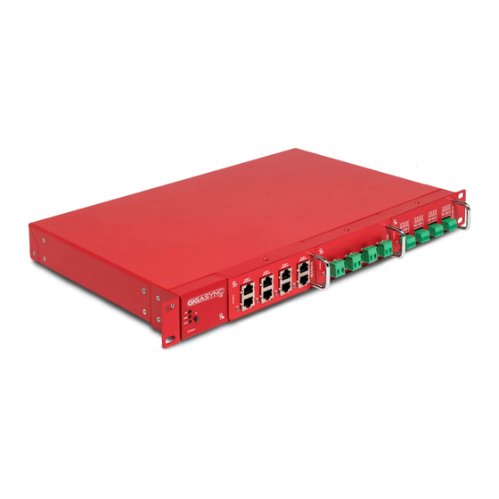
General description GigaSync is designed to supply power to devices through the Power over Ethernet standard or directly through terminals. It consists of a base unit that can house up to 3 expansion cartridges. The base unit contains the main interface and the control systems, the cartridges define the supply power method: by PoE, bipolar terminals, or by 4-poles terminals. -
Page 7: Gigasync Features
Multiple and redundant temporization source GigaSync has a built-in GPS receiver and can act as a master or slave with other units such as GigaSync or uGPS, cnPulse, and CMM5 (of Cambium Networks). More power Up to 3A (145W@48V) each port PoE or power supply terminal. -
Page 8: Base Unit
It also has SYNC INPUT and SYNC OUTPUT ports used respectively to acquire or replicate the synchronous pulse. ETHERNET PORT The base unit can also be powered via the Ethernet connector, compatible with passive PoE. GIGASYNC MANUAL VER. 3 REV. 1... -
Page 9: Unit Base Label
Unit base label This device will have a label attached with relevant information as described below. Figure 4 – Example of GigaSync unit base label As we can see, on the label it is indicated: The product code: GS-B-V3, with a brief description. -
Page 10: Cartridges
On both sides, there are slots for inserting GigaKey keys that allow you to select the output pin of the PoE port without the use of micro switches to provide PoE to a wide range of devices. Through the main connector located behind, the module is connected to the internal electronics of the GigaSync. GIGASYNC MANUAL... -
Page 11: Terminal's Cartridge: Gs-G-Ter
Each terminal has a signaling LED that provides information on the status of the door and any faults. Each connector can be removed from the terminals for easier manipulation. Through the main connector located behind, the module is connected to the internal electronics of the GigaSync. GIGASYNC MANUAL... -
Page 12: Terminal's Cartridge With Synchronization: Gs-G-Ter-Cs
Each terminal has a signaling LED that provides information on the status of the port, on any faults, and if Cambium Sync synchronization is active or not. Each connector can be removed from the terminals for easier manipulation. Through the main connector located behind, the module is connected to the internal electronics of the GigaSync. See the section “GigAdapter” GIGASYNC MANUAL... -
Page 13: Cartridge Label
Indications by the standards FCC, CE, and RoHS. The image of the garbage container indicates that this equipment should not be placed in household containers. Instead, it must be disposed of properly in compliance with current regulations. GIGASYNC MANUAL VER. 3 REV. 1... -
Page 14: Technical Specifications
Synchrony; Status and Alarm Rear LED indicators 7 LED indicates the presence of voltage at the input SYNCHRONIZATION SPECIFICATIONS GPS external connector Type N female Sync input compatibility GigaSync of 9dot; uGPS , cnPulse and CMM5 of Cambium Networks ® ® ®... - Page 15 2000 A, 8/20 μs | 100 A, 8/20 μs | 10 A, 10/1000 μs | 2 A, 50 Hz, 1 sec Gigabit transformer Canopy Sync Cambium Sync (#) Only with GigaSync V3 (version 3), values pending certification. GIGASYNC MANUAL VER. 3 REV. 1...
- Page 16 If, on the other hand, we choose the GS-G-POE-CS cartridge with GigaKey GS-K-AB or GS-K-9.S, in the base unit GS-G- V3 (version 3), we will be able to power up to 4 devices that consume a total of 12A. See section “GigaKey” See the following example GIGASYNC MANUAL VER. 3 REV. 1...
-
Page 17: Installation
Installation The GigaSync is designed for installation in a 19” rack cabinet, however, the fixing tabs can be rotated 90° for wall mounting. Figure 9 - GigaSync with fixing tabs at 90° IMPORTANT NOTE: Use only the fixing screws supplied with the device for fixing the fins; the use of different fixing screws can cause irreparable damage to the device. -
Page 18: Physical Interface
(*) Restore the password of the admin user to the default configuration. Through the interface, you can also choose to reset the IP address. LED coding Base unit To know the general status of the GigaSync, are considered the first 3 LEDs arranged vertically to the left of the front. Color Description... -
Page 19: Blocks Diagram
(•) a CPU guarantees the correct operation of all the basic electronics and performs the voltage and current measurement (•) another different CPU manages the user interface (•) the power components are isolated from the rest The following is a schematic detail of the GigaSync design structure. ETHERNET MAIN INPUT POWER INPUT POWER 1... -
Page 20: Input Power
The power supply is individual for each cartridge, that is, each pair of connectors is isolated from the rest and from the power supply of the base unit. No conversion is applied to the input voltage and there is no isolation between input and output. GIGASYNC MANUAL VER. 3 REV. 1... -
Page 21: Special Case -48V
Power can be supplied in two ways through GigaSync: through the PoE injectors or the bipolar terminals. On the one hand, in the case of PoE injectors, there are two types of cartridges that we can choose to add to our GigaSync, with or without a synchronization pulse: ... -
Page 22: Gigabit Injector Gs-G-Poe
This protection works as follows: If there is a short circuit on the connected load, the GigaSync will turn off the port to protect itself so as not to damage the device. After a few seconds it reactivates the door, always with the protection active; if the short circuit is still present then the protection trips again and will continue without powering the load until the situation normalizes, retrying every few seconds and indefinitely. -
Page 23: Gigabit Injector Gs-G-Poe-Cs
Table 6 – Pinout GigaKey (*) These are just some of the devices that can work with GigaSync. The list is very long, if you want to know if your equipment can connect to GigaSync, do not hesitate to contact us. -
Page 24: Power Gs-G-Ter
It is a passive device, designed to bring power and synchronization from the 4-pole connector of the TER-CS to an RJ45 connector, to be able to use a standard network cable for the device, combining it with the optical fiber for data passage. Figura 13 - GigAdapter image GIGASYNC MANUAL VER. 3 REV. 1... -
Page 25: Synchronization
GPS antenna The external antenna must be connected to the N-type female connector that is installed on the back of the GigaSync and requires a good view of the sky. It does not need to be mounted at the highest point of the tower. - Page 26 CMM5 is a cluster management module manufactured by Cambium Networks that replicates the device's sync pulse through an output port. If you have a CMM5 in your configuration, you can get the sync pulse and connect it to the GigaSync sync input port.
-
Page 27: Types Of Configurations
One GPS antenna for two GigaSync: It is an option that allows you to minimize costs. In this case, the GPS antenna will be connected to a GigaSync via the coaxial cable and the 2 GigaSync will be connected via the Sync Input / Sync Output ports. -
Page 28: Connect With The Gigasync
Figure 14 – Schema of connection to communicate with GigaSync by SSH, Web and SNMP interfaces In addition, it can be connected directly from a computer to the RJ45 port located on the back of the GigaSync. The operating system performs all the functions of the interface with the user through the control panel accessible through the web interface. - Page 29 Indicating that the IP address has been permanently added to the list of known hosts. After that, it will ask us for the password, and we must enter the default one: "password" As soon as you log in, the 9dot logo will appear as shown below: To see all possible menus and commands, type "?" and press "enter".
-
Page 30: Menu
(*) IMPORTANT NOTE: In case of "shutdown", the interface cannot be reactivated. To reactivate it, it is necessary to turn off all power supplies for a few seconds. Then turn it on again and reconnect. GIGASYNC MANUAL VER. 3 REV. 1... -
Page 31: Snmp Interface
-v 3 -l authNoPriv -u admin -a sha -A "password" -m ./genmib.mib <IP GigaSync> .1.3.6.1.4.1.48108 Note that the complete sentence must be copied as is, writing the IP number of the GigaSync where it says “<IP GigaSync>”. For the MIBs to display correctly, execute the command in the folder containing the "genmib.mib" file downloaded from the interface or indicate the complete path of the file. -
Page 32: Web Interface
There are two ways to connect to the GigaSync: Ethernet and Wi-Fi. For the Wi-Fi connection we must look for the SSID "GSvx_#" generated by GigaSync itself. The # symbol indicates the serial number shown on the label attached to the device. -
Page 33: Interface Description
Interface description The web interface has an intuitive design that allows total remote management of the GigaSync, it is specially designed to facilitate access from mobile devices since it has a responsive design, to be able to adapt graphically and automatically to the device with which it is displayed. -
Page 34: Options Bar
We will describe the functions of each of the buttons on the bar below. Stop The Stop button deactivates all GigaSync outputs. After pressing it, it will ask if we are sure. ATTENTION: This deactivates all outputs of the GigaSync but does not disconnect it from its power sources. - Page 35 Yellow: warning Green: Informative Each message will have the time and date of the event to facilitate diagnosis. IMPORTANT NOTE: To automatically synchronize the day and time of the log, GigaSync must be connected to a network with internet access. User The user option allows access to some actions related to the web interface itself.
- Page 36 Sign out: Close the session directly and the identification window will appear on the screen, requesting the login credentials again. Whether for "System reset", "Hardware reboot" or "Reboot", the interface will ask us for confirmation by entering the password. GIGASYNC MANUAL VER. 3 REV. 1...
-
Page 37: Synoptic Diagram
Synoptic diagram The synoptic diagram illustrates the structure of the system including the modules installed in the GigaSync device, the status of each element and some values of interest, easy to discern, such as: Instantaneous input voltage y values of absorbed current of each cartridge ... -
Page 38: Modules
If this is not displayed, the change may not have been made. General information View general GigaSync information, including input line voltage, and total output current. You can also view the internal temperature of each cartridge. Figura 20 - System overview... - Page 39 Figure 21 – Information about control module Network In Network you can change all the network settings and activate Wi-Fi and NAT, to access the network through GigaSync. Figure 22 - CMD module network menu We can also obtain and modify the data of: ...
- Page 40 Logs Logs record all the warning or error messages reported by GigaSync with different colors depending on the priority (red, yellow and green) and with the date and time. When there are new notifications, a red number appears on the dashboard bell indicating the number.
- Page 41 Power cycle port Spegne e riaccende l'uscita in automatico Sync port Solo nelle cartucce PoE-CS e TER-CS, consente di abilitare il tipo di sincronia desiderato Rename port Rinomina la porta, per una migliore comprensione dell'impianto GIGASYNC MANUAL VER. 3 REV. 1...
- Page 42 Sync cascade: if activated, it allows to replicate of the acquired sync pulse on the SYNC-OUT port. Figure 25 - GPS & SYNC module information Se clicchiamo sul pulsante "View on Google Maps" si aprirà Google Maps con la posizione del GPS. GIGASYNC MANUAL VER. 3 REV. 1...
-
Page 43: Software Update
Revision update To update the software, the file containing the update must be uploaded to the GigaSync via FTP. We recommend using FileZilla, a free and open-source FTP solution that you can find at the following link: https://filezilla-project.org/ To perform the software update procedure, you must complete the following steps: •... - Page 44 Confirm the installation by typing "y", if you are sure. Wait for the confirmation of successful installation, the phrase "System updated successfully!" Should appear. Exit SSH with the “exit” command. GIGASYNC MANUAL VER. 3 REV. 1...
-
Page 45: Official Distributors
08015 Barcelona, Spain Abbey, Headquarters Dublin 7, Ireland Avenida de la Industria, 32 28108 Madrid, Spain +353 1 871-6316 Offices sales.emea@winncom.com (+34) 933 90 59 54 www.winncom.com Headquarters (+34) 918 29 77 85 info@wifidom.com www.wifidom.com GIGASYNC MANUAL VER. 3 REV. 1... - Page 46 9dot is a registered trademark of 9dot S.r.l in the European Union and the United Kingdom. Copyright © 2020 9dot. GigaSync is a registered trademark of 9dot S.r.l. in the European Union and the United Kingdom. Copyright © 2017 9dot.
Need help?
Do you have a question about the GigaSync and is the answer not in the manual?
Questions and answers