Advertisement
Table of Contents
- 1 Door Switch - Specifications
- 2 Mounting the Door Switch
- 3 Controller Operation with Door Switch Activated
- 4 Setting up the Controller for Use with a Door Switch Using the Controller’s Web Page
- 5 Setting up the Controller for Use with a Door Switch Using the Controller’s Display
- 6 Accessing the Menus
- 7 Additional Resources
- Download this manual
Installing the KE2 Therm Door Switch
Configuring Ethernet Enabled Controllers: KE2 Evaporator Efficiency, KE2 Evap for Rack Efficiency &
KE2 Controlled Environment
Configuring Non-Ethernet Enabled Controllers: KE2 Low Temp & KE2 Adaptive Control
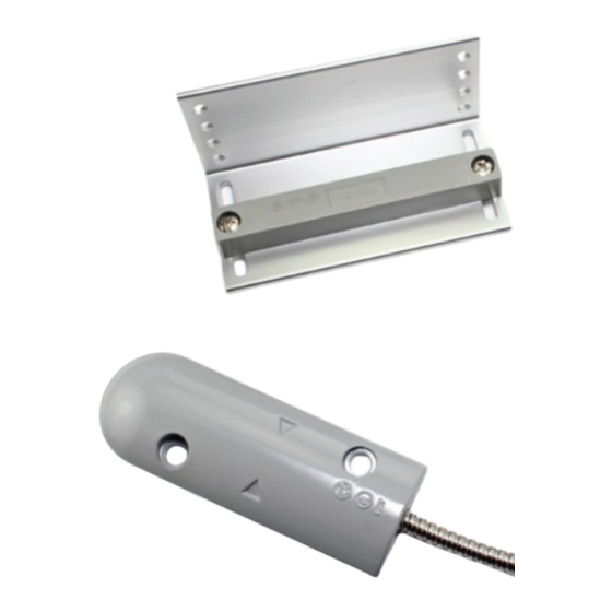
Basic Description
Designed to withstand rugged
high traffic installations, the door
switch provides increased energy
efficiency, more stable product
temperature, and is effective at
preventing coil freeze ups. The reed
switch is hermetically sealed with
a PVC shock absorber, enclosed
within a solid aluminum housing.
Installation wires are protected in a
24" (61 cm) stainless steel armored
cable. The magnet is mounted on
an adjustable L shaped bracket
providing
greater
flexibility,
universal mounting, higher pulling power, and a professional
appearance.
Controller Operation with Door Switch Activated
Normal system operation while the door is closed.
When the door is opened, evaporator fans are turned off.
If the door is left open for longer than 60 seconds, the sole-
noid (EEV) is closed to initiate system pumpdown.
System will remain in pumpdown until door is closed.
If the door is left open for time set in Door Alarm Delay (de-
fault is 30 min.) and the temperature rises 5°F (2.8°C) above
setpoint, a Door Alarm is activated and the system is turned
back on to resume cooling
Once the door is closed, normal system operation resumes.
Mounting the Door Switch
The door switch mounts in any position along the door, how-
ever the gap between the magnet
sensor
B
cannot exceed 2" (5 cm) when the door is closed.
If the gap is greater than 2" (5 cm) the door switch will contin-
ually signal that it is open, and the controller will turn off the
evaporators. To help the installer adjust the gap, the L-bracket
has
C
multiple mounting holes, and the magnet can moved
forward, or backward, in the slot
Attach to
the door
C
multiple holes
A
for exibility
when mounting
D
magnet can be
adjusted forward or
backward in the slot
© Copyright 2017 KE2 Therm Solutions, Inc., Washington, Missouri 63090
Door Switch - Specifications - pn 20543
A
and the contact assembly/
D
.
L-Bracket
Magnet
Armored
Cable
2 ft. (61 cm)
Contact Assembly
B
Attach to
the wall
Contact
22AWG
Contact Rating
10VA
Contact Type
Normally Open
Max Carry Current
2 Amp
Max Switching
.5 Amp
Current
Breakdown Voltage 250 VDC
Operating Gap
2 inches (5 cm)
Temperature Range 32°F to 120°F (0°C to 49°C)
Housing Material
solid aluminum housing
Cable Length
24" (61 cm) stainless steel armored cable
Certifications
UL and ULC listed
Position
The Contact Assembly / Sensor mounts in any
The magnet can mount to the
postion,as long as it is within two inches of the
inside of the L-Bracket or the
magnet, when the door is closed.
outside.
L-Bracket &
Magnet Options
Top of Door
Q.1.27 February 2017
thermsolutions
TM
KE2 EvaporatorEfficiency
2
2
ENTER
BACK
Side of
Door
Advertisement
Table of Contents

Summary of Contents for KE2 20543
- Page 1 Q.1.27 February 2017 Installing the KE2 Therm Door Switch Configuring Ethernet Enabled Controllers: KE2 Evaporator Efficiency, KE2 Evap for Rack Efficiency & KE2 Controlled Environment Configuring Non-Ethernet Enabled Controllers: KE2 Low Temp & KE2 Adaptive Control Basic Description Designed to withstand rugged...
- Page 2 Configuring Non-Ethernet Enabled Controllers: NO NC Setting the KE2 Evap, KE2 Evap for Rack Efficiency, or KE2 Controlled Environment for use with a door switch. 3A Relay NOTE: Screen shots shown are representative of the procedure. They will vary slightly based on the controller being installed, and 3A Relay on the version of firmware.
- Page 3 Q.1.27 February 2017 Page 3 Installing the KE2 Therm Door Switch KE2 Evaporator Efficiency, KE2 Evap for Rack Efficiency & KE2 Controlled Environment Configuring Ethernet Enabled Controllers: KE2 Low Temp & KE2 Adaptive Control Configuring Non-Ethernet Enabled Controllers: Setting up the controller for use with a door switch using the controller’s display KE2 Evaporator Efficiency, KE2 Evap for Rack Efficiency &...
- Page 4 Q.1.27 February 2017 Page 4 Installing the KE2 Therm Door Switch KE2 Evaporator Efficiency, KE2 Evap for Rack Efficiency & KE2 Controlled Environment Configuring Ethernet Enabled Controllers: KE2 Low Temp & KE2 Adaptive Control Configuring Non-Ethernet Enabled Controllers: Setting up the controller for use with a door switch using the controller’s display KE2 Low Temp + Defrost &...
Need help?
Do you have a question about the 20543 and is the answer not in the manual?
Questions and answers