Table of Contents
Advertisement
Quick Links
CEDRAT TECHNOLOGIES S.A.
59 Chemin du Vieux Chêne – Inovallée
38246 MEYLAN CEDEX
CCBU40 COMPACT CONTROLLER BOARD
PRODUCT AND WARRANTY INFORMATION
Version: 1.21
Date: 11/03/2021
www.cedrat-technologies.com • actuator@cedrat-tec.com • Tél : +33 (0)4 56 58 04 00
SA au capital de 550 000 € • RCS GRENOBLE 310 416 334 • SIRET 310 416 334 00046 • TVA intracommunautaire FR 29 310 416 334 • RIB BNP MEYLAN FRANCE 30004 01285 00028
016118 94 • IBAN FR76 3000 4012 8500 0280 1611 894 • SWIFT BNPAFRPPGRE
Advertisement
Table of Contents

Summary of Contents for Cedrat Technologies CCBu40
- Page 1 CEDRAT TECHNOLOGIES S.A. 59 Chemin du Vieux Chêne – Inovallée 38246 MEYLAN CEDEX CCBU40 COMPACT CONTROLLER BOARD PRODUCT AND WARRANTY INFORMATION Version: 1.21 Date: 11/03/2021 www.cedrat-technologies.com • actuator@cedrat-tec.com • Tél : +33 (0)4 56 58 04 00 SA au capital de 550 000 € • RCS GRENOBLE 310 416 334 • SIRET 310 416 334 00046 • TVA intracommunautaire FR 29 310 416 334 • RIB BNP MEYLAN FRANCE 30004 01285 00028...
-
Page 2: Caution: Read Before Opening
If any damage is found, a claim should be filed with the carrier. The package should also be inspected for completeness according to the enclosed packing list. If an order is incorrect or incomplete, contact your distributor. CCBU40 COMPACT CONTROLLER BOARD - PRODUCT AND WARRANTY INFORMATION Version 1.21... -
Page 3: Information On Disposal For Users Of Waste Electrical & Electronic Equipment (Private Households)
Except as expressly indicated in writing, Cedrat Technologies products are not designed for use in medical, life- saving, or life-sustaining applications or for any other application in which the failure of the Cedrat Technologies product could result in personal injury or death. -
Page 4: Table Of Contents
XI.3. HDPM45 GUI ................................27 XII. POWER SUPPLY, POWER CONSUMPTION, OUTPUT CURRENT CAPABILITY ......... 27 XIII. THERMAL INTERFACE ..........................29 XIV. TROUBLE SHOOTING FORM ........................31 XV. ANNEX I: MECHANICAL ICD ........................32 CCBU40 COMPACT CONTROLLER BOARD - PRODUCT AND WARRANTY INFORMATION Version 1.21... -
Page 5: Introduction
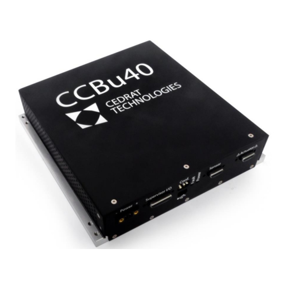
Refer to chapter VIII The bottom of the packaging features the mechanical interfaces to attach the CCBu40. The bottom plate is also a thermal interface used to dissipate the heat of the CCBu40. The packaging features side openings for air circulation to enhance the heat dissipation. - Page 6 The CCBu40 only requires a single DC power supply between +24Vdc - +28Vdc to operate. Two status LEDs indicate the condition of the system. The green LED “Power” indicates that the CCBu40 is powered on, and the red LED “Fault” indicates if a fault condition has been detected or if the CCBu40 is disabled. The board integrates overtemperature detection, overload detection, and missing connector detection.
-
Page 7: Ccbu40 Configuration
In default configuration the control parameters are the following: P=0.05, I=200, D=0. Output filter is a second order lowpass filter with cutoff frequency of 200Hz. When the CCBu40 is associated with a mechanism, these parameters could be tuned to reach the mechanism performances. This information is given in the the mechanism Factory Verification Sheet. -
Page 8: Architecture
8 / 32 V.3. ARCHITECTURE The architecture of the CCBu40 is represented schematically on the Figure 2 or Figure 3 depending on the selected sensor. On the figure, the commands for adjusting the configuration are identified with ‘’ marks. The details of the commands are given in Section 0. - Page 9 9 / 32 can then be read as a voltage on the “T°C” analog output of the supervisor connector. The CCBu40 integrates a conditioner that provides a constant 1.613mA current to the PT1000 probe. Based on the voltage measurement on the “T°C” output, the temperature in °C is computed as follows: Temperature [°C] = (“T°C”...
- Page 10 59 Chemin du Vieux Chêne – Inovallée 38246 MEYLAN CEDEX Figure 2 : Architecture of the CCBu40 with integrated SG conditioner Important warning: The numbering on the Figure 2 and Figure 3 does not correspond to the pinouts of the connectors. For connectors pinout, please refer to chapter Electrical connectionsVIII.
- Page 11 11 / 32 Figure 3 : Architecture of the CCBu40 with external sensor option Important warning: The numbering on the Figure 2 and Figure 3 does not correspond to the pinouts of the connectors. For connectors pinout, please refer to chapter Electrical connectionsVIII.
-
Page 12: Modes Of Operation
OPEN AND CLOSE LOOP OPERATION The CCBu40 can operate in closed-loop or in open-loop. In open loop, the user commands are directly sent to the power drives. In closed loop, the CCBu40 controls the system position based on the sensor feedback and user commands. - Page 13 Figure VI-1: Example of rising and falling time measurement The second test (Linearity) compares in open loop the output voltage vs the input order. The amplifier gains are calculated. Figure VI-2: Example of linearity measurement CCBU40 COMPACT CONTROLLER BOARD - PRODUCT AND WARRANTY INFORMATION Version 1.21...
-
Page 14: Mechanical Installation
The side of the packaging features 8x M3 through all holes to allow mounting on a wall: Figure 3: Threaded holes for installation Detailed mechanical ICD can be found in Annex. The bottom surface of the CCBu40 serves as a heatsink. Please check Section XIII for heatsinking requirements. -
Page 15: Electrical Connections
For protection against electric shock, connectors must be isolated from the power supply while being assembled or disassembled. Never perform electrical connections when the CCBu40 is powered-on. The CCBu40 provides high voltage outputs to the piezo actuators (>100V), and there is a risk of electrical shock. -
Page 16: Viii.1. Interface With The Client / Supervisor
16 / 32 VIII.1. INTERFACE WITH THE CLIENT / SUPERVISOR For the interface of the CCBu40 with the client supervisor, the connector is a micro D-Sub25. Figure 4 : Supervisor interface Pin N° Signal Description Comment Analog sensor output for Y axis ±10V output. -
Page 17: Viii.2. Power Supply Connector
VIII.2. POWER SUPPLY CONNECTOR Figure 5. CCBU40’s Supply connector and its mating connector (Phoenix Contact: 1714977). The pin 1 (on the left of the connector) must be connected to the 0V and the pin 2 (on the right) must be connected to the +28V. -
Page 18: Ii) Sensor Connector
VIII.1. EARTHING INTERFACE The CCBu40 must be connected to ground / earth using the ground interface.This is an M3 interface, for a ring cable lug. CCBU40 COMPACT CONTROLLER BOARD - PRODUCT AND WARRANTY INFORMATION... -
Page 19: Starting And Operating The Ccbu40
The CCBu40 startup is controlled with the “Enable” digital input on the supervisor connector. When the “Enable” signal is high (3.3V) or undriven, the CCBu40 remains in standby, and power converters are not activated. In this mode, no motion can be applied to the actuators. In standby, the “Fault” LED and “Fault” signal are set to indicate that the system cannot operate. -
Page 20: Control
The sensor feedback must be in phase with the piezo voltage. This can be checked by operating the CCBu40 in open loop, the sensor should be in phase with the command. If this is not the case (in particular with the external sensor option), there is the possibility to adjust and invert the sensor feedback gain in software if needed. -
Page 21: Communication Interface
The digital link serves to set the control parameters and can also serve to send the commands and read sensors. The CCBu40 can be interfaced and configured manually over the serial link It offers compatibility with the HDPM45 GUI provided by CTEC for its controllers (see section XI.3) Note: The communication becomes active as soon as the green “Power”... -
Page 22: Xi.2. Standard Format
(‘+’ or ‘-‘), and decimal separator ‘.’. It is not authorized to leave this field empty. If unused it can be filled with ‘0’. The parameters to the CCBu40 can be integer of floating values. - Page 23 If the ‘M4.678E’ sets the upper limit controller output is larger, it will be saturated to ‘M’ [-1V ; +7.5V] of the output at 4.678V. this value. CCBU40 COMPACT CONTROLLER BOARD - PRODUCT AND WARRANTY INFORMATION Version 1.21...
- Page 24 This only changes the gain of the sensor in software, the analog sensor signals are not impacted. This gain is set to 1 by default. In standard configurations, it is recommended to leave it unchanged. CCBU40 COMPACT CONTROLLER BOARD - PRODUCT AND WARRANTY INFORMATION Version 1.21...
- Page 25 19198 -0.01% 38400 38396 -0.01% 57600 57692 0.16% 115200 114796 -0.35% 230400 229592 -0.35% 460800 468750 1.73% 921600 937500 1.73% Table 2 : Parameter value for typical baud rate CCBU40 COMPACT CONTROLLER BOARD - PRODUCT AND WARRANTY INFORMATION Version 1.21...
- Page 26 For instance a value of 15001 means serial number 15-001 (year of manufacturing 2015, CCBu40 N°1) Not used (last 4 data bytes before acknowledgement) Acknowledgement character ‘X’ Table 3: Description of parameter set read back CCBU40 COMPACT CONTROLLER BOARD - PRODUCT AND WARRANTY INFORMATION Version 1.21...
-
Page 27: Xi.3. Hdpm45 Gui
The power consumption of the CCBu40 is approximately 6W in static operation. Static operation means that the CCBu40 is enabled, no error is detected, and the commands are steady, i.e. the system is not moving. In dynamic operation, i.e. when the system is moving, the power consumption will increase linearly with the increase of output current to the piezo ceramics. - Page 28 28 / 32 Figure 9: Power consumption vs total output current CCBU40 COMPACT CONTROLLER BOARD - PRODUCT AND WARRANTY INFORMATION Version 1.21...
-
Page 29: Thermal Interface
There is a risk of burns when touching the packaging. The bottom plate of the CCBu40 is the heat sinking surface. To prevent from overheating at high temperature and/or high power, the user must implement proper heat sink for cooling. This can be done by attaching a spare heatsink, or directly by attaching the CCBu40 on a surface providing heat dissipation. - Page 30 30 / 32 Figure 10: Maximum thermal resistance depending on the power consumption, at +70°C. Figure 11: Maximum thermal resistance depending on the ambient temperature, at 95W. CCBU40 COMPACT CONTROLLER BOARD - PRODUCT AND WARRANTY INFORMATION Version 1.21...
-
Page 31: Trouble Shooting Form
Problem identification: Please summarise and describe here, using the “notations”, the operation that could lead to problem identification, Action: Please mention and update here every action undertaken by yourself, by Cedrat Technologies or by your local vendor, Please note that you need to get the authorisation from CEDRAT TECHNOLOGIES before sending back the hardware. -
Page 32: Annex I: Mechanical Icd
CEDRAT TECHNOLOGIES S.A. 59 Chemin du Vieux Chêne – Inovallée 38246 MEYLAN CEDEX XV. ANNEX I: MECHANICAL ICD www.cedrat-technologies.com • actuator@cedrat-tec.com • Tél : +33 (0)4 56 58 04 00 • Fax : +33 (0)4 56 58 04 01 SA au capital de 550 000 € • RCS GRENOBLE 310 416 334 • SIRET 310 416 334 00046 • TVA intracommunautaire FR 29 310 416 334 • RIB BNP MEYLAN FRANCE 30004 01285 00028 016118 94 • IBAN FR76 3000 4012 8500 0280 1611 894 • SWIFT...
Need help?
Do you have a question about the CCBu40 and is the answer not in the manual?
Questions and answers