
Summary of Contents for KRK KNA NETWORK ANALYZER
- Page 1 KNA NETWORK ANALYZER GARANT NETWORK ANALYZER KNA 96 USER GUIDE Phone: 444 4 575 web:www.krk.com.tr...
- Page 2 GENEL ÖZELL KLER GENERAL FEATURES WARNING 1.Cut all power before connecting device. LCD display 2.Do not connect the current measurement inputs 3 voltage measuring inputs directly to the current source. Always connect 3 current measuring inputs the current source using a current transformer. Communication via Rs485 3.
- Page 3 APPLICATIONS 1. Voltage Inputs L1----1st Phase Voltage input KNA Network Analyser is microprocessor-based L2----2nd Phase Voltage input device which is designed to measure all parameters of an electrical network, calculate L3----3rd Phase Voltage input N-----Neutral NPUT the consumption values and display these on its LCD screen.
- Page 4 ADJUSTMENT BUTTON FUNCTIONS First of all we have to enter current transformer ratio SET BUTTON ( ) : Press SET button for device and necessery parameters into device. adjustment. Press SET ( ) button HARMONIC BUTTON ( ) : When you press Harmonic button ( ) you can see current and You will see below screen.
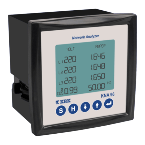
- Page 5 Ntn : Network communication number You will see below screen. Press UP( )/DOWN( ) button to enter network number. Press ENTER button again to return to main screen. 00001 OPERATING When you power up the system you will see voltages , current, frequency and cosfi values for L1, L2, L3 phases.
- Page 6 If you press UP ( ) button again , respectively you When you press DOWN ( ) button you can will see kW, kVArL/ kVArC values for each phases on see phase to phase voltages and current the screen. When you press DOWN button again you will see L1, L2 , L3 Cosfi values.
-
Page 7: Harmonics Measurement
Otomatik kademe (güç) tanıtma HARMONICS MEASUREMENT TECHNICAL SPECIFICATIONS When you press Harmonics ( ) button you can see Power Supply : 220 Vac ±15%(N-L1) 50 Hz Current and voltages harmonics for each phases Power Consumption : < 2VA To return back press ( ) button.
Need help?
Do you have a question about the KNA NETWORK ANALYZER and is the answer not in the manual?
Questions and answers