Table of Contents
Advertisement
Quick Links
Advertisement
Table of Contents

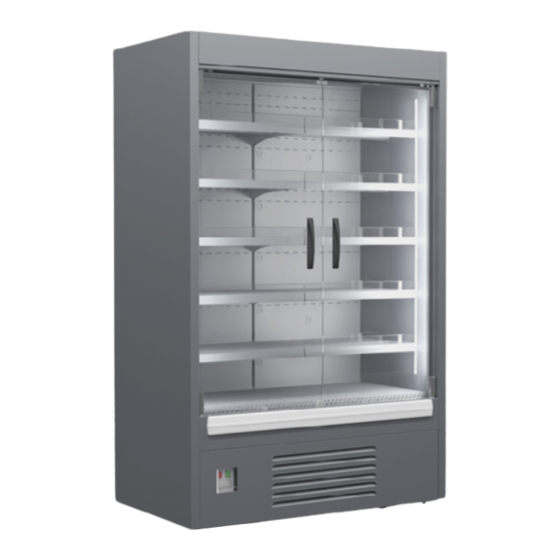
Summary of Contents for JUKA ADI125
-
Page 2: Table Of Contents
OPERATING INSTRUCTIONS FOR UPRIGHT REFRIGERATED CABINET (REGAL) ADX Dear Customers! Read the manual of the upright refrigerated cabinet before you start using it, which will ensure long and efficient operation of the equipment! Table of contents 1. General information ......4 4.2.2.Checking the set temperature . - Page 3 Dear customer! If you have purchased equipment operating with R290 refrigerant, please read the reservations carefully before using this product. Special warning notes for equipment with R290 refrigerant Fluorinated greenhouse gases are in a hermetically sealed system. Work on the refrigeration and electrical systems of the equipment should only be performed by the manufacturer's qualified service technician.
-
Page 4: General Information
1. GENERAL INFORMATION Upright refrigerated cabinet ADX is designed for short-term storage and sale of food, previously cooled to the temperature of the cooled volume in retail stores and catering establishments. The cabinet is designed to be used indoors at ambient temperature from +16 to +25°C and relative humidity of no more than 60%. The temperature inside the cabinet is 2°C + 8°C. -
Page 5: Technical Specifications
2. TECHNICAL SPECIFICATIONS Units of Parameters ADI125 ADI150 ADX95 ADX125 ADX150 ADX187.5 ADX250 measurement Dimensions: 1250 1500 1250 1500 1875 2500 Length without side panels Length with side panels 1310 1560 1035 1335 1585 1960 2585 Depth Height 2085 2085... -
Page 6: Transportation, Installation And Commissioning
3. TRANSPORTATION, INSTALLATION AND COMMISSIONING 3.1. Transportation method The unit requires careful protection against damage and accidental overturning during transportation. Glass elements and painted surfaces are especially vulnerable. The equipment must be in an upright (working) position both when transporting and when moving. After installing the equipment in a specific location, the network connection must be made after a minimum of 6 hours. - Page 7 DO NOT: • cover and block the ventilation openings of the equipment; • install the equipment near heat sources (heaters, radiators) and under direct sunlight; • install the equipment in draughts. If the requirements are not met, air circulation is impaired and product performance deteriorates, which can lead to food spoilage. The product compressor works cyclically, switching off when the set temperature is reached and switching on when the temperature rises by 2-3°C.
-
Page 8: Operation Of Energy-Saving Night Blinds (Curtains)
4. If the power cord is damaged, it must be replaced by the manufacturer or the manufacturer's service technician or a qualified electrician in order to prevent any possible damage to life or health. 5. DO NOT connect the cabinet through extension cords that do not have a grounding wire, or if the cross-sectional area of the extension cord is less than 1.5 sq. -
Page 9: Assembling A Line Of Refrigerated Multideck Adx
3.7. Assembling a line of refrigerated multideck ADX 3.7.1. Remove the front glass from the connecting windows by removing it from the groove. - Page 10 3.7.2. Remove the shelves and brackets that hold them from the side of the multideck joint. To do this, lift the shelf up to the exit of the brackets holding it out of the grooves, after the shelf is removed - remove the brackets from the grooves in the racks.
- Page 11 3.7.3.Remove the upper and lower perforated false walls, in 3.7.4. Remove the front panel, take the panel from under the the center of the false wall is a hole for interaction with it. Hook bottom and pull on yourself, then feed the panel to the bottom to the the false wall through this hole with your finger, lift it slightly exit upper flanges with hook.
- Page 12 3.7.5.Unscrew the self-tapping screws and remove the rack plugs on the connection side...
- Page 13 3.7.6. If the side panel is installed - unscrew the bolts securing it and remove the side panel (note, for convenience, it is recommended to place under the side panel supports made of soft material (wood, plastic, foam, etc.) to prevent fall side panel and paint damage).
- Page 14 3.7.6. If the side panel is installed - unscrew the bolts securing it and remove the side panel (note, for convenience, it is recommended to place under the side panel supports made of soft material (wood, plastic, foam, etc.) to prevent fall side panel and paint damage).
- Page 15 3.7.7. Apply a butyl cord d = 4 mm at the junction of the display case. In the case of connecting display case without a partition - application to only one of the display cases.
- Page 16 3.7.8. Only for the option of installing a blank panel !!! Attach the blank panel with M6x16 bolts (use two M6x25 bolts at the bottom of the panel), similarly attach the second multideck to the panel on the opposite side. (note, for convenience it is recommended to substitute supports made of soft material (wood, plastic,...
- Page 17 3.7.9. Only for the option of connecting without partitions !!! Install the air duct plug, for which you need to put the cap on the flange of the upper panel while inserting the deflection of the cap between the foam insert and the bends of the parts...
- Page 18 3.7.10. Connect the display cases to each other, or through a jumper made of plexiglass through the upper bracket and side post with bolts M6x16 (M6x25 when using a partition made of plexiglass), connect the two lower mounts of the frame with M6x45. Secure the connection with M6 self-locking nuts...
-
Page 19: Operation
4. OPERATION 4.1. Operating procedure of the CAREL electronic controller 4.1.1. Light signals on the electronic controller display • Indicating LEDs on the display Light signal a - compressor: the symbol is visible when the compressor is running. Blinks if the compressor start is delayed by a safety procedure. Light signal b - fan: The symbol lights up when the fans are on. -
Page 20: Checking The Set Temperature
4.2.2. Checking the set temperature. • Press briefly the SET button (8), then the set temperature will appear on the screen; • Press the SET button (8) briefly or wait for 5 seconds to return to the normal display. 4.2.3. Temperature change. To change the set values:: •... -
Page 21: Cleaning The Equipment
2. The electrical part does not require any maintenance other than visual inspection of the external protective or insulating materials. 3. Periodically perform a visual inspection of the cold volume fans for operability and presence of debris. To do this, remove the lower shelves (Figure 6 ) (1 - right lower shelf, 2 - shelf extraction insert, 3 - left lower shelf, 4 - front panel) 4. -
Page 22: Miscellaneous
Holding the front panel by its bottom part, pull it toward you until the front panel comes out of the support brackets, then lower the front panel until it comes out of the upper slots, pull the panel out Figure 8. Front panel Figure 9. - Page 23 • Check that the equipment is properly aligned. • Check the drainage system for permeability. • Empty the container or condensate tray. If the power cord is damaged: • If the power cord is damaged, it must be replaced in order to avoid a hazard. To do this, contact the service department, the manufacturer, or qualified personnel.
-
Page 24: Disposal
This phenomenon is a technical property of the refrigeration equipment and is not a sign of malfunction. If, after checking the items mentioned above, the equipment does not work correctly, contact JUKA Technical Center, indicating the data from the nameplate. - Page 25 ATTENTION! Keep the warranty card for the entire duration of the warranty period. With this warranty, the seller and the service center assume the obligation to remedy defects caused by the manufacturer at no charge during the warranty period. The warranty card is valid only if it correctly and clearly indicates: the model, serial number of the equipment, date of sale, clear seal of the seller.
- Page 26 Warranty card Date of sale Product and model Serial number Warranty period The buyer confirms the technical serviceability of the product/ Seller's signature Buyer's signature...
Need help?
Do you have a question about the ADI125 and is the answer not in the manual?
Questions and answers