Table of Contents
Advertisement
Quick Links
INSTRUCTION MANUAL
KEW MATE 2000A/2001A
KYORITSU ELECTRICAL INSTRUMENTS
WORKS, LTD.
Buzzer
5.PREPARATIONS FOR MEASUREMENT
(1)Checking battery voltage
Set the Function Selector Switch to any position other than the OFF position.
I f the marks on the display is clearly legible without symbol "BATT" showing, battery
voltage is OK. If the display blanks or "BATT" is indicated, replace the batteries
according to section 8: Battery Replacement.
When the instrument is left powered on, the auto-power-save function automatically
shut the power off; The display blanks even if the Function Selector Switch is set to
a position other than the OFF position in this state. To power on the instrument,
turn the Function Selector Switch or press the Data Hold Button. If the display still
blanks, the batteries are exhausted. Replace the batteries.
(2)Make sure that the Function Selector Switch is set to the appropriate range.
A lso make sure that data hold function is not enabled. If inappropriate range is
selected, desired measurement cannot be made.
(3)Install Test Lead to the Holster on the side of body
I t is possible to measure with seeing the LCD Display keep
Test Lead installing to the Holster.
1.800.561.8187
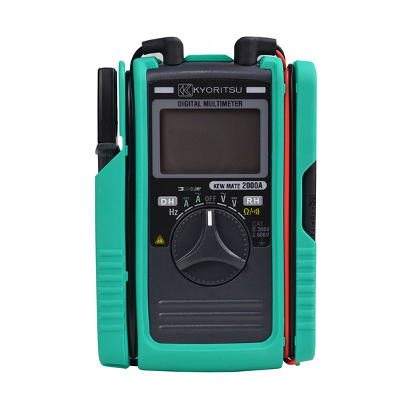
DIGITAL MULTIMETER
WITH
AC/DC CLAMP SENSOR
Battery Voltage Warning
Data Hold
Auto Range
Unit
AC/DC
Manual
Range
AC/DC Clamp Sensor
Test Leads
Wind the lead around the folder.
NOTE
www.
1.SAFETY WARNINGS
This instrument has been designed and tested according to IEC Publication 61010:
Safety Requirements for Electronic Measuring Apparatus. This instruction manual
contains warnings and safety rules which must be observed by the user to ensure
safe operation of the instrument and to retain it in safe condition. Therefore, read
through these operating instructions before starting using the instrument.
● R ead through and understand
starting using the instrument.
● S ave and keep the manual handy to enable quick reference whenever necessary.
● B e sure to use the instrument only in its intended applications and to follow
measurement procedures described in the manual.
● B e sure to understand and follow all safety instructions contained in the manual.
The instrument is to be used only in its intended applications.
Understand and follow all the safety instructions contained in the manual.
Failure to follow the instructions may cause injury, instrument damage and/or
damage to equipment under test. Kyoritsu is by no means liable for any damage
resulting from the instrument in contradiction to this cautionary note.
Failure to follow the above instructions may cause injury, damage to the instrument
and/or damage to equipment under test.
The symbol indicated on the instrument means that the user must refer to related
parts of the manual for safe operation of the instrument. Be sure to carefully read the
instructions following each symbol in this manual.
DANGER i s reserved for conditions and actions that are likely to cause serious or fatal injury.
WARNING is reserved for conditions and actions that can cause serious or fatal injury.
CAUTION i s reserved for conditions and actions that can cause minor injury or instrument damage.
Following symbols are used on the instrument and in the instruction manual. Attention
should be paid to each symbol to ensure your safety.
Refer to the instructions in the manual.
This symbol is marked where the user must refer to the instruction manual so as not
to cause personal injury or instrument damage.
Indicates an instrument with double or reinforced insulation.
Indicates that this instrument can clamp on bare conductors when measuring
a voltage corresponding to the applicable Measurement category, which is marked
next to this symbol.
Indicates AC (Alternating Current).
Indicates DC (Direct Current).
Indicates AC and DC.
● N ever make measurement on circuits with a maximum voltage difference of
600VAC/DC or greater between conductors (300VAC/DC or greater between a
conductor and ground).
● D o not attempt to make measurement in the presence of flammable gasses.
Otherwise, the use of the instrument may cause sparking, which leads to an
explosion.
● N ever attempt to use the instrument if its surface or your hand is wet.
●Do not exceed the maximum allowable input of measuring ranges.
● N ever open the battery compartment cover while making measurement.
● N ever try to make measurement if any abnormal conditions, such as broken
Transformer jaws or case is noted.
● T he instrument is to be used only in its intended applications or conditions.
Otherwise, safety functions equipped with the instrument doesn t work, and
instrument damage or serious personal injury may be caused.
6.HOW TO MAKE MEASUREMENT
6-1 Current Measurement
● I n order to avoid possible shock hazard, never make measurement on circuits with a
maximum voltage difference of 600VAC/DC or greater between conductors
Bar Graph
(300VAC/DC or greater between a conductor and ground).
● D o not make measurement with the test leads connected to the circuit under test.
Never make measurement with the battery compartment cover removed.
●Keep your fingers and hands behind the barrier during measurement.
● W hen handling the clamp sensor, exercise caution not to apply excessive shocks or
vibration to the sensor.
M
●
aximum measurable conductor size is MODEL2000A 6mm / MODEL2001A
10mm in diameter.
Correct
6-1-1 DC Current Measurement
(1)The Function Selector Swith to the " A" position.
("DC" and "AUTO" marks are shown on the top of the display.)
(2) T urn the 0(Zero) ADJ knob to set the reading of the multimeter to zero. (If this zero
adjustment is made incorrectly, measurement errors will result.)
(3) A djust one of the conductors to the center of the clamp sensor's arrow.
( When the position of the conductor is not at the center of the arrow, the error
occurs.)
Measured value is shown on the display.
Note: W hen current flows from the upside to the underside of the instrument, the polarity
of the reading is positive (+). Otherwise, the polarity of the reading is negative (-).
6-1-2 AC Current Measurement
(1)Set the Function Selector Switch to " A."
("AC" and "AUTO" marks are shown on the top of the LCD.)
(2) A djust one of the conductors to the center of the clamp sensor's arrow.
( When the position of the conductor is not at the center of the arrow, the error
occurs.)
Measured value is shown on the display.
Note: U nlike DC current measurement, zero adjustment is not necessary. There is not
polarity indication either.
6-2 Voltage Measurement
● I n order to avoid possible shock hazard, never make measurement on circuits with a
maximum voltage difference of 600VAC/DC or greater between conductors
(300VAC/DC or greater between a conductor and ground).
● D o not make measurement with the battery compartment cover removed.
●Keep your fingers and hands behind the protective fingerguard during measurement.
6-2-1 DC Voltage Measurement
(1)Set the Function Selector Switch to " V."
("DC" and "AUTO" marks are shown on the top of the LCD.)
(2) C onnect the red test lead to the positive (+) side of the circuit under test and the
black test lead to the negative (-) side. Measured voltage value is shown on the
display.
When the connection is reversed, "-" is shown on the display.
.com
WARNING
instructions contained in this manual before
DANGER
DANGER
CAUTION
Conductor
Adjust a
conductor to
the center of
the arrow.
Wrong
MODEL2000A
MODEL2001A
DANGER
information@itm.com
Advertisement
Table of Contents

Related Manuals for Kyoritsu Electrical Instruments Works KEW MATE 2000A

Summary of Contents for Kyoritsu Electrical Instruments Works KEW MATE 2000A
- Page 1 WITH Indicates AC (Alternating Current). AC/DC CLAMP SENSOR Indicates DC (Direct Current). Indicates AC and DC. KEW MATE 2000A/2001A DANGER ● N ever make measurement on circuits with a maximum voltage difference of 600VAC/DC or greater between conductors (300VAC/DC or greater between a KYORITSU ELECTRICAL INSTRUMENTS conductor and ground). ● D o not attempt to make measurement in the presence of flammable gasses. ...
- Page 2 2.FEATURES WARNING ● N ever attempt to make any measurement, if any abnormal conditions are noted, ● P ermits AC/DC current measurement up to 60A using a clamp sensor that comes such as broken case, cracked test leads and exposed metal parts. standard with the instrument ● D o not turn the Function Selector Switch while the test leads are connected to the ●Clamp sensor for ease of use in crowded cable areas and other tight places circuit under test. ● P ermits current measurement with an open current-clamp sensor that does not require ● ...
- Page 3 ●Location for use I ndoor use, Altitude up to 2000m 3.SPECIFICATIONS ●Accuracy-insured 23℃±5℃, relative humidity 75% or less Temperature and (without condensation) ●Measuring Ranges and Accuracy (at 23℃±5℃, relative humidity75% or less) Humidity Ranges AC Current A ●Operating Temperature ...
Need help?
Do you have a question about the KEW MATE 2000A and is the answer not in the manual?
Questions and answers