Table of Contents
Advertisement
Quick Links
Advertisement
Table of Contents

Related Manuals for Grason-Stadler GSI Corti


Summary of Contents for Grason-Stadler GSI Corti
- Page 1 DPOAE TEOAE DEVICE CORTI USER MANUAL...
- Page 2 5500 Middelfart Denmark Copyright © 2020 Grason-Stadler. All rights reserved. No part of this publication may be reproduced or transmitted in any form or by any means without the prior written permission of GSI. The information in this publication is proprietary to GSI.
-
Page 3: Table Of Contents
ABLE OF ONTENTS Table of Contents ........................1 Preface ............................5 Manual Conventions ......................5 Regulatory Symbols ......................6 Warnings and Cautions ......................9 Important Safety Instructions ....................9 Safety Precautions ........................ 9 Charging ..........................11 Electric Shock Hazard ......................11 Explosion .......................... - Page 4 Probe Holder ........................19 Operating Instructions ......................20 Preparing the Patient for Testing ..................20 Turning On the Instrument ....................20 Control Panel ........................20 Main Menu .......................... 21 Selecting the Test Protocol ....................21 Starting a Test ........................22 AutoStart Probe Check .......................
- Page 5 Clock Mode .......................... 37 Graph Style .......................... 37 Norms ..........................37 Reverse Frequency......................38 Auto Stop ..........................38 Language ..........................38 Reset to Default........................38 Advanced Options ........................39 DPOAE Diagnostic Unit ....................... 39 Instructions for Customizing a Test Protocol ..............39 Selecting the Level of Primary Tones ................
- Page 6 Appendix E: Configurations and Test Protocols ..............62 Diagnostic Configurations ....................62 DPOAE Diagnostic Default Protocols................. 63 TEOAE Diagnostic Default Protocols ................. 64 GSI Corti Screening Configurations ................... 64 DPOAE Screening Default Protocols.................. 65 TEOAE Screening Default Protocols .................. 65 Appendix F: Standards Compliance ..................66 Appendix G: Specification of Input/output Connections .............
-
Page 7: Preface
This operating manual contains information pertinent to the use of the GSI Corti system including safety information as well as maintenance and cleaning recommendations. -
Page 8: Regulatory Symbols
EGULATORY YMBOLS Symbol Description Serial Number Date of Manufacture Manufacturer Caution, Consult Accompanying Documents Return to Authorized Representative, Special Disposal Required Reference Number B Patient Applied Part According to IEC60601-1 Consult Operating Instructions Keep Dry Transport and Storage Temperature range Logo EC REP EU Authorized Representative... - Page 9 A copy of the operating manual is available on this website: www.grason-stadler.com A printed copy of the operating instructions can be ordered from Grason-Stadler for shipment within 7 days; or you can contact your local representative. D-0103241Rev H Page 7 of 76...
- Page 10 A copy of the operating manual is available on this website: www.grason-stadler.com A printed copy of the operating instructions can be ordered from Grason-Stadler for shipment within 7 days; or you can contact your local representative. Indicates that the device is a Medical Device Class II medical equipment...
-
Page 11: Warnings And Cautions
ARNINGS AND AUTIONS MPORTANT AFETY NSTRUCTIONS The following safety precautions must be observed always. General safety precautions must be followed when operating electrical equipment. Failure to observe these precautions could result in damage to the equipment and injury to the operator or patient. The instrument must only be used by hearing health care professional qualified to perform otoacoustic tests such as an audiologist, otolaryngologist, researcher or a technician under the direct supervision by the specialist. - Page 12 Latex is not used anywhere in the manufacturing process. The base material for the ear tips is made from silicone rubber. The device is not intended to be used in environments exposed to fluid spills. No means is specified for fluid protection (not IP classed). Do not use the device in the presence of fluid that can contact any of the electronic components or wiring.
-
Page 13: Charging
HARGING The Corti Otoacoustic Emission Test System should be charged using only the provided power supply. Injury to personnel or damage to equipment can result when a three-prong to two-prong adaptor is connected between the Corti power supply and an AC outlet. LECTRIC HOCK AZARD... -
Page 14: Introduction
NDICATIONS The GSI Corti series is indicated for testing of cochlear function in infants, children and adults by measuring otoacoustic emissions (OAEs). The OAEs are generated by a series of clicks that are directed into the ear canal. Otoacoustic emissions are low level audio- frequency sounds that are produced by the cochlea as part of the normal-hearing process. -
Page 15: How Does The Corti Device Work
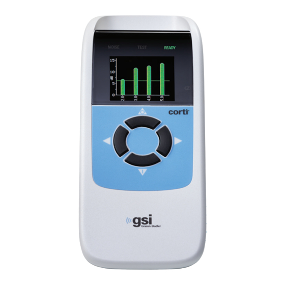
OES THE ORTI EVICE The system consists of the instrument, probe, printer, single- Probe use eartips replaceable probe tubes and other accessories. The Corti Test Status instrument contains the hardware Indicators and software for generating the test stimuli, measuring and displaying Display the OAEs, and storing the results Charge Status... -
Page 16: What Are Teoaes
TEOAE Transient Evoked Otoacoustic Emissions (TEOAEs) are acoustic signals that can be detected in the ear canal of a person with normal outer hair cell function, after stimulation of the auditory system with a series of wideband clicks. The Corti instrument generates a series of clicks, directs them into the ear canal, and then analyzes the spectrum of the returning signal, separating the noise and emission. -
Page 17: Sensitivity And Specificity
ENSITIVITY AND PECIFICITY Sensitivity and specificity of this type of device are based on the test characteristics defined by the user and may vary depending on environmental and operating conditions. The presence of otoacoustic emissions suggests normal outer hair cell function, which in turn correlates to normal hearing. -
Page 18: Setup
NPACKING THE YSTEM The following parts are shipped standard with each Corti system: Corti Unit Corti Probe GSI Corti Software and Manuals USB GSI Suite Software and Manuals USB Single Use Eartip Kit Communications Cable, USB A/Micro-B Charging Cable, PSU 5V/Micro-B... -
Page 19: Battery Charging
ATTERY HARGING The Corti instrument is powered by an integrated rechargeable lithium-ion battery providing 20hours of operation between full charging. The battery status is indicated by the battery icon shown in the upper right corner of the Main Menu. Full battery charge is represented by a full battery symbol on the display and reduces to an empty battery in increments corresponding to the discharge of the battery. -
Page 20: Installing The Probe
NSTALLING THE ROBE Insert the Probe’s HDMI connector firmly into the socket on the top of the Corti. The plug will fit in only one direction. The GSI wave logo will align with the instrument control panel. NOTE: Misalignment of the plug and socket can cause damage. The plug and socket should be visually inspected prior to each installation of the remote probe. -
Page 21: Probe Holder
After selecting an eartip, push it onto the probe tube until it is flush against the base of the probe tube. Twisting the eartip slightly while pushing it onto the probe tube is recommended. Be sure the eartip is fully seated on the probe. -
Page 22: Operating Instructions
PERATING NSTRUCTIONS REPARING THE ATIENT FOR ESTING Otoscopic examination of the patient’s ear canals should be performed prior to testing. Excessive cerumen or vernix in the ear canals may interfere with the test and give invalid or incomplete results. Patients with excessive cerumen, debris, or foreign bodies in the ear canals should be referred to an audiologist or physician for removal of the blockage prior to testing. -
Page 23: Main Menu
Selected Protocol Battery Status Date & Time Number of Stored Tests Start Right Start Left Ear Test Ear Test Change Protocol and Settings ELECTING THE ROTOCOL The currently selected protocol is shown on the Main Menu. To change the selected protocol press CHANGE at the Main Menu. The Change Protocol display will appear. -
Page 24: Starting A Test
TARTING A To obtain a seal and measure emissions, gently insert the eartip into the patient’s ear canal. It should fit snugly and comfortably. The best test results are obtained when an eartip is inserted deeply into the ear canal instead of flush with the ear canal. To begin a test, insert the probe into the ear and select either the LEFT or RIGHT... -
Page 25: Test Phase
NOTE: To test children with PE tubes, the Probe Check needs to be disabled. This is accomplished by first inserting the probe with appropriate ear tip into the ear canal and obtaining a proper seal. To disable AutoStart at the Main Menu select the ear to be tested by holding down the RIGHT or LEFT arrow keys for 3 seconds until the green “ready”... -
Page 26: Value Graph View
ALUE RAPH The Value graph view for left ear test displays dark blue “x” symbols representing the absolute emission levels at each DP test frequency or TE frequency band. Light blue upside-down triangles represent the noise floor at each DP test frequency or TE frequency band. - Page 27 push the DOWN arrow key to return to the bar graph. After reviewing the results, again push the DOWN arrow key to return to the Results display or the up arrow to return to the Main Menu. The Corti will display the both Right and Left results at the end of the test, when in Save L/R Mode.
-
Page 28: Viewing Dpoae Results With Normative Data
DPOAE R IEWING ESULTS WITH ORMATIVE The Corti will display the Expanded Boys Town Norms template for eligible DPOAE test results. The norms template has no effect on the overall test results and is for display purposes only. The values used to create the template are from Gorga, M.P., Neely, S.T., Ohlrich, B., Hoover, B., Redner, J. -
Page 29: Test Technique
ECHNIQUE As with other otoacoustic emission test instruments, there is a technique to learn when using the Corti instrument, especially while testing infants. Experience with existing OAE systems suggests that it may take up to 3 months to become completely proficient at screening infants. -
Page 30: Managing Results
GSI Data Manager database or utilizing Auto Print. Specific options will vary depending on the configuration of the system purchased. GSI Corti test results may be transferred into GSI Suite. See GSI Suite user manual for more information. NOTE: Results from screening protocols (DP 2s, DP 4s, TE 32s, TE 64s) may be stored ®... -
Page 31: Deleting Results
screen, use the left or right arrows to cycle through the names until the desired name is on the display. A patient named “Unnamed” is always included at the beginning of the Corti list for instances when a patient is being tested but the patient name was not transferred to the Corti. -
Page 32: Printing To A Thermal Printer
RINTING TO A HERMAL RINTER Printing to an optional thermal printer is by way of wireless connection. First establish wireless pairing between the Corti instrument and the printer by following the instructions in the section Instrument Settings - Wireless Device Pairing. NOTE: See the printer operating manual for instructions on using the printer. -
Page 33: Connecting To The Corti Data Manager
ONNECTING TO THE ORTI ANAGER For the PC to Corti connection, plug the USB-A connector into an available USB port on the computer and the Micro-USB of the cable into the port found at the base of the Corti instrument. For the PC to Corti Cradle connection, plug the USB-A of the cable into a computer USB port and the USB-B connection to the back port of the Cradle. -
Page 34: Rounding Results
11) The noise floor (NF) in dB SPL 12) The emission level (DP) in dB SPL 13) The signal-to-noise ratio (SNR)- DP level minus the noise floor – in dB 14) A “P” to the right of the SNR if pass criteria were met for that frequency 15) The Value or SNR graph as selected on the Corti 16) “MIN*”... -
Page 35: Clock Settings
printout values are rounded up to the nearest integer and are shown as DP = 6, NF = 0, and SNR = 6. This can result in what appears to be an error regarding the pass criterion. If the pass criterion is 6 dB while the actual SNR is 5.9, the printed value will be 6 but the frequency will not be judged as a PASS with a “P”... -
Page 36: Instrument Settings
NSTRUMENT ETTINGS The Corti instrument allows the user to change many of the instrument's settings or functions. These settings include Wireless Device Pairing, Clearing Test Results, Auto Power Off Time, Save Mode, Minimum Amplitude Value, Clock Mode, Graph Mode, DPOAE Norms On/Off, DPOAE Reverse Frequency, DPOAE Auto Stop, Language, and Reset to Default Settings. -
Page 37: Clearing Test Results
LEARING ESULTS The Test Results Clear menu allows the user to clear the test results stored in the unit without printing them. Select the LEFT or RIGHT arrow key to clear the results and select Yes or No to verify clearing or to cancel. To advance to the next menu without clearing the results, press NEXT. -
Page 38: Minimum Amplitude Value
2. If the Corti Data Manager is used to transfer patient names to the Corti, the Corti will display the names. When numbers are used (no patient names are uploaded from the Data Manager to the Corti), each test is automatically incremented, starting with test number 1. When patient names are used (patient names are uploaded from the Corti Data Manager to the Corti unit) the patient names are displayed on the Corti Unit in alphabetical order. -
Page 39: Clock Mode
LOCK The Clock Mode menu allows the user to change the clock from a 24 hour mode to a 12 hour mode. To change the clock mode, press the CHANGE keys. Press the NEXT to exit this menu. When 12 hour mode is selected, AM or PM will appear in the time/date screen. -
Page 40: Reverse Frequency
EVERSE REQUENCY The Rev FREQ setting allows for reversing the presentation of the test frequencies from ‘low frequency to high frequency’ to ‘high frequency to low frequency’ for DPOAE protocols. For example, when Rev Freq is off, the 4s protocol frequency order is 2.0, 3.0, 4.0, and 5.0 kHz. -
Page 41: Advanced Options
DVANCED PTIONS DPOAE D IAGNOSTIC The Advanced Options menus permit modification of the test parameters and pass criterion for the customizable protocols on the DP Diagnostic unit. Changes to the protocol should be made only by qualified personnel, usually the administrator. If you are not familiar with the use of these variables, do not attempt to change the protocols. -
Page 42: Selecting The Level Of Primary Tones
Selecting the Level of Primary Tones The intensity of the primary tones (L1, L2) may be changed to any level between 40 dB SPL and 70 dB SPL. The level L1 will change in 1 dB increments by pushing the LEFT or RIGHT arrow keys and press NEXT to move to the L2 screen. -
Page 43: Setting The Number Of Frequencies For Pass
Setting the Number of Frequencies for PASS The number of frequencies required for determining a PASS can be set from 0 to 12 depending on the protocol selected. If the setting is on 0, then no indication of PASS/REFER will be made. -
Page 44: Save Protocol
Save Protocol Once all the settings have been selected for the protocol, these settings can be saved by selecting the SAVE keys. Press the NEXT key to exit. NOTE: If a protocol has been modified, an * will appear in the protocol name. For example, if protocol DP 2.0-5.0 has been modified, it will appear on the Corti as DP*2.0-5.0. -
Page 45: Selecting The Averaging Time
NOTE: If you push the DOWN arrow key without holding it for 3 seconds, you will scroll through date and time, etc., rather than accessing the displays that allow you to make changes to the custom protocols. Selecting the Averaging Time The maximum Averaging Time has four available settings. -
Page 46: Setting The Number Of Frequencies For Pass
Setting the Number of Frequencies for PASS The number of frequencies for determining a PASS can be set from 0 to 6. If the setting is on 0, then no indication of PASS/REFER will be made. This setting is used in conjunction with the PASS SNR to set the criteria for the overall test PASS/REFER indication. -
Page 47: Cleaning And Maintenance
LEANING AND AINTENANCE LEANING AND ISINFECTION Use a new eartip for each patient. Eartips are for single patient use only. The probe tube, which does not make direct contact with the patient, should be replaced if there is any sign of contamination or if the test will not progress past the AutoStart phase. Disinfection of the probe tube between patients is not required. -
Page 48: Maintenance
AINTENANCE This instrument requires no regular maintenance beyond routine cleaning and annual calibration. The probe tube requires replacement only when it becomes clogged. A defective product should not be used. Make sure all connections to external accessories are snug and secured properly. Parts which may be broken or missing or are visibly worn, distorted or contaminated should be replaced immediately with clean, genuine replacement parts manufactured by or available from GSI. -
Page 49: Status/Error Messages
TATUS RROR ESSAGES ISPLAY ESSAGES Attach Probe No probe is detected at the start of a test. Device not The printer is not responding to queries from the instrument. Responding Wireless Device The paired wireless device cannot be detected. The device may Not Found be turned off or too far away. -
Page 50: Indicator Leds (Lights)
Due for Service Reminder will appear when the calibration due date has passed. NDICATOR LIGHTS NOISE / Orange The indicator labeled ‘NOISE’ provides a visual indication (AMBER) that the noise level measured during the test exceeds a nominal threshold. Also used to indicate some error conditions and when the outcome of test is REFER, NOISY, or NO SEAL. -
Page 51: Troubleshooting
ROUBLESHOOTING Problem Solutions Instrument does The DOWN arrow must be pressed for a full second (the • not turn on Yellow test LED will illuminate). Connect the charger and confirm that blue "Charging" LED is • illuminating in a slow blink pattern. Wait at least 10 minutes and then attempt to turn on the instrument •... - Page 52 TE screening test is Re-insert probe tip into ear canal • paused Reposition the probe tip • • Wait for noise levels to decrease; test will resume Attach • Probe not detected. Check that the probe connector is fully seated in the socket. Probe •...
- Page 53 Fit Error For a DP test, the level of the calibration tone is too high. User • should refit the probe and retry the test. Too High Replace the probe tube. • Contact GSI for service if problem persists across several •...
-
Page 54: Appendix A: Specifications
A: S PPENDIX PECIFICATIONS PROBE SPECIFICATIONS Distortion Product Otoacoustic Emissions Measurement Type: (DPOAE) Transient Evoked Otoacoustic Emissions (TEOAE) Frequency Range: DPOAE: 1.5 to 12 kHz TEOAE: 0.7 to 4 kHz Stimulus Intensity Range: DPOAE: 40 to 70 dB SPL TEOAE: 80 dB SPL peak equivalent (±3 dB) Microphone System Noise: -20 dB SPL @ 3 kHz (1 Hz bandwidth) / -13 dB SPL @ 1 kHz (1 Hz bandwidth) -
Page 55: Power Supply Specifications (Use Only Approved Power Supply)
based database programs or an optional PC printer HDMI Connector for connection to the Probe Integrated wireless Class 2 + EDR with SPP Protocol for communication with optional printer POWER SUPPLY SPECIFICATIONS ( USE ONLY APPROVED POWER SUPPLY Model No: UE08WCP-050160SPA Output: 5.0V DC, 1.6A... -
Page 56: Appendix B: Flowcharts
B: F PPENDIX LOWCHARTS EASUREMENT To Start: Press DOWN arrow Press UP arrow to return to Main Menu D-0103241Rev H Page 54 of 76... -
Page 57: Setup Menus
ETUP ENUS Press and hold DOWN arrow for three seconds to enter next menu Clock Menu System Menu DP Settings TE Settings D-0103241Rev H Page 55 of 76... - Page 58 D-0103241Rev H Page 56 of 76...
-
Page 59: Appendix C: Test Sequence
C: T PPENDIX EQUENCE A complete test sequence consists of an AutoStart, calibration, and test phase. The AutoStart phase determines when the calibration phase should proceed, while the calibration phase calibrates the level of the tones that will be applied during the actual test phase. -
Page 60: Comment About Variations In The Snr Estimate
most of the data in the test. However, as the level of the noise becomes more variable over time, the instrument will attempt to accept the quieter portions of the recording. Noise estimates are obtained approximately 32 times per second and a suitable threshold is estimated from the data. -
Page 61: Appendix D: Pass/Refer Criteria
D: P PPENDIX EFER RITERIA DPOAE The decision that a DPOAE exists is based on detecting a signal whose level is significantly above the background noise level. This requires a statistical decision, since the random noise level in the DPOAE filter channel can be expected to exceed the average of the random noise levels in the four adjacent filter channels —... -
Page 62: Teoae
TEOAE The same basic principles that underlie DPOAE Pass/Fail criteria underlie TEOAE Pass/Fail criteria. In the case of transients, requiring SNR of 4 dB at any three out of the six test frequencies drops the probability of passing an ear with a significant hearing loss to less than 1%. - Page 63 The artifact rejection can only reject the noisiest samples in a measurement period. If the ambient noise level rises too high (and/or the eartip seal is poor), then all samples will be noisy and accurate measurements will be impossible, in which case the test result will indicate “noisy.”...
-
Page 64: Appendix E: Configurations And Test Protocols
E: C PPENDIX ONFIGURATIONS AND ROTOCOLS IAGNOSTIC ONFIGURATIONS Configuration Protocols Included DP Diagnostic: DP 4s (default - not customizable) DP 2.0-5.0 DP 1.5-6.0 DP 1.6-8.0 DP 1.5-12 TE Diagnostic: TE 64s (default - not customizable) TE 1.5-4.0 TE 0.7-4.0 DP and TE Diagnostic DP 4s (default - not customizable) Combo:... -
Page 65: Dpoae Diagnostic Default Protocols
DPOAE D IAGNOSTIC EFAULT ROTOCOLS Passing Freq. for Protocol # of Averaging Pass Test Name Freqs F2 Frequency* L1/L2 Time Pass 2.0, 3.0, 4.0, 5.0 DP 4s 65/55 4 sec 6 dB 2.0, 3.0, 4.0, 5.0 DP 2.0-5.0 65/55 4 sec 6 dB 1.5, 2.0, 3.0, 4.0, DP 1.5-6.0... -
Page 66: Teoae Diagnostic Default Protocols
TEOAE D IAGNOSTIC EFAULT ROTOCOLS # of Frequency Averaging # Passing Protocol Frequency Center Time Pass Freq. for Name Bands Bands (max) Test Pass 1.5, 2, 2.5, 3, TE 64s 64 sec 4 dB 3.5, 4 kHz 1.5, 2, 2.5, 3, TE 1.5-4.0 64 sec 4 dB... -
Page 67: Dpoae Screening Default Protocols
DPOAE S CREENING EFAULT ROTOCOLS Passing Freq. for Protocol # of Averaging Pass Test Name Freqs F2 Frequency* L1/L2 Time Pass 2.0, 3.0, 4.0, 5.0 DP 2s 65/55 2 sec 6 dB 2.0, 3.0, 4.0, 5.0 DP 4s 65/55 4 sec 6 dB * Frequency pairs are presented at a F2/F1 ratio of 1.22. -
Page 68: Appendix F: Standards Compliance
F: S PPENDIX TANDARDS OMPLIANCE Standard Title ANSI/ASA 3.6 Specification for Audiometers IEC 60601-1 Medical Electrical Equipment – General Requirements for Basic Safety and Essential Performance, Ed. 3.1 IEC 60645-1 Electroacoustics - Audiological equipment -- Part 1: Pure- tone audiometers IEC 60645-3 Electroacoustics - Audiometric equipment -- Part 3: Test signals of short duration... -
Page 69: Appendix G: Specification Of Input/Output Connections
PPENDIX PECIFICATION OF NPUT OUTPUT ONNECTIONS OAE P ROBE Description REC 1 + REC 1Shield REC 1 - REC 2 + HDMI Type A REC 2 Shield REC 2 - MIC Power + MIC Shield MIC Out Mic Power - Not Used Not Used Not Used... -
Page 70: Appendix H: Warranty
PPENDIX ARRANTY We, Grason-Stadler, warrant that this product is free from defects in material and workmanship and, when properly installed and used, will perform in accordance with applicable specifications. If within one year after original shipment, it is found not to meet this standard;... -
Page 71: Appendix I: Recycling And Disposal
Follow all local laws and regulations for the proper disposal of batteries and any other parts of this system. Below is the contact address for proper return or disposal of electronic wastes relating to Grason-Stadler products in Europe and other localities. The contact information for the WEEE in Europe: Grason-Stadler... -
Page 72: Appendix J: Electromagnetic Compatibility
Portable and Mobile RF communications equipment can affect the GSI Corti. Install and operate the GSI Corti according to the EMC information presented. The GSI Corti has been tested for EMC emissions and immunity as a standalone instrument. Do not use the GSI Corti adjacent to or stacked with other electronic equipment. - Page 73 Guidance and Manufacturer’s Declaration - Electromagnetic Emissions The GSI Corti is intended for use in the electromagnetic environment specified below. The customer or the user of the GSI Corti should assure that it is used in such an environment. Emissions Test...
- Page 74 Communications Equipment and the GSI Corti The GSI Corti is intended for use in an electromagnetic environment in which radiated RF disturbances are controlled. The customer or the user of the GSI Corti can help prevent electromagnetic interferences by maintaining a minimum distance between...
- Page 75 Guidance and Manufacturer’s Declaration - Electromagnetic Immunity The GSI Corti is intended for use in the electromagnetic environment specified below. The customer or the user of the Corti should assure that it is used in such an environment. Immunity Test...
- Page 76 5% UT 5% UT the Corti be powered from an (>95% dip in UT) (>95% dip in UT) uninterrupted for 5 sec for 5 sec power supply. Power Frequency 3 A/m 3 A/m Power frequency (50/60 Hz) magnetic fields should be at levels characteristic of a IEC 61000-4-8 typical location in a...
- Page 77 Guidance and Manufacturer’s Declaration - Electromagnetic Immunity The GSI Corti is intended for use in the electromagnetic environment specified below. The customer or the user of the Corti should assure that it is used in such an environment. Immunity IEC 60601...
- Page 78 Note 1: At 80 MHz and 800 MHz, the higher frequency range applies. Note 2: These guidelines may not apply to all situations. Electromagnetic propagation is affected by absorption and reflection from structures, objects and people. (a*) Field strengths from fixed transmitters, such as base stations for radio (cellular/cordless) telephones and land mobile radios, amateur radio, AM and FM radio broadcast and TV broadcast cannot be predicted theoretically with accuracy.
Need help?
Do you have a question about the GSI Corti and is the answer not in the manual?
Questions and answers
Why are our responses purple in color and not green? They still seem robust but are not green to indicate pass.