Sunfire Theater Grand Processor III User Manual
Hide thumbs
Also See for Theater Grand Processor III:
- User manual (60 pages) ,
- Control manual (5 pages) ,
- User manual (61 pages)
Table of Contents
Advertisement
Quick Links
SIG NA L PR
OC ESS ING
DO LBY
DIG ITA L
Su n fi re T he
ZON E TW
O
POW ER
DTS
ZON E TW
O
ADJ UST
PRO LOG
IC II
HO LOG RAP
HIC
IMA GE
DIG ITA L
SOU RCE
SID E-A XIS
PO WE R
1
2
3
4
MA NU AL
AM /FM
DIR ECT
Ar chi tec t's
TUN ING
Ch oic e
DO WN
TU NE R CO
NT RO LS
at er G ra n d
P ro ce ss or II
I
ROT ATI ON
MO DE
DO WN
UP
ZON E
TW O
HO LOG RAP
HIC
IMA GE
5
6
7
8
TRE BLE
9
0
PAN EL
+10
DIM
SEL ECT
BAS S
MU TE
UP
S u n fi re
DO WN
UP
TO NE CO
NT RO LS
FUL L AUT
OM ATI C
OPE RAT ION
MA NU AL
LE VE L
INP UT SEL
EC TO R
Advertisement
Table of Contents

Related Manuals for Sunfire Theater Grand Processor III


Summary of Contents for Sunfire Theater Grand Processor III
- Page 1 SIG NA L PR OC ESS ING DO LBY DIG ITA L Su n fi re T he ZON E TW POW ER at er G ra n d P ro ce ss or II ZON E TW ADJ UST PRO LOG IC II HO LOG RAP...
-
Page 2: Safety Instructions
SAFETY Safety In struc tions 8. Power Sources — The Com po nent 13. Damage Re quir ing Service should be con nect ed to a power sup- — The Com po nent should be serviced ply only of the type de scribed in these only by qualifi... - Page 3 SAFETY 15. To prevent electric shock, do not 16. Grounding or Po lari za tion — ATTENTION — Le présent appar- use this polarized plug with an ex ten - Pre cau tions should be taken so that eil numérique n'émet pas de bruits sion cord, receptacle or other outlet the grounding or polarization means radioélectriques dépassant las limites...
-
Page 4: Table Of Contents
CHAPTER 1 Contents Safety Instructions........2-3 Read the Safety Instructions care- fully before connecting and us- Chapter 1: Introduction .......5 ing your Sunfi re Theater Grand Processor III (TGIII). Unpacking and Features ......6 Overview.............7 Chapter 1 is a general introduction to the features, details and installa- Quick Start Guide ........8 tion of your TGIII. -
Page 5: Chapter 1: Introduction
Bob Carver, Audio Designer, Physicist Dear Friend, Thank you for pur chas ing my Sunfi re Theater Grand Processor III. I hope that you enjoy it and the music it makes as much as I have en joyed creating it for you. -
Page 6: Unpacking And Features
S-video and composite video side outputs for a total of 9.1 your Theater Grand Processor III ever channels • Three A/V outputs, each with au- needs to be moved or shipped for dio, S-video and composite video •... -
Page 7: Overview
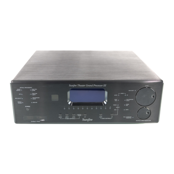
Tuner Tone input presets con trols con trols Mute The Theater Grand Processor III is available in two versions: • 17” wide chassis model, • 19” wide chassis model, The illustrations in this manual designed as an ideal match for show the Architect’s Choice model. -
Page 8: Quick Start Guide
13. The TGIII now needs to be setup will help you get started using your a few times to make sure you correctly to suit your speakers and Theater Grand Processor III. are on the Main Menu in the system. The following On Screen remote's display. - Page 9 CHAPTER 1 13.3 In the MAIN Menu, select the 13.5 In the SPEAKERS Menu, select 14. If you play a Dolby Digital or DTS SETTINGS Menu, and then the the CALIBRATION Menu to adjust encoded source, the TGIII will SPEAKERS Menu. the output of each speaker.
-
Page 10: Front Panel Features
CHAPTER 1 Front Panel Features Sunfire Theater Grand Processor III LEVEL SIGNAL PROCESSING DOLBY ZONE TWO DIGITAL POWER ROTATION ZONE TWO MODE ADJUST DOWN HOLOGRAPHIC PRO LOGIC II IMAGE ZONE HOLOGRAPHIC IMAGE DIGITAL SIDE-AXIS SOURCE PANEL TREBLE POWER SELECT BASS... - Page 11 CHAPTER 1 Front Panel Features 6. Level 10. Tuner Controls 12. Full Au to mat ic Operation Rotate this manual control clock- AM/FM wise to increase the volume. This button toggles between When this is engaged, the The dB level will appear in the the AM or FM band.
-
Page 12: Rear Panel Features
RIGHT RIGHT SUR RB SUR VIDEO VID1 VID2 MAIN VID2/MON2 DIGITAL AUDIO INPUTS VID1 VID1 DIGITAL OUT IEEE Sunfire Corporation 1394 Theater Grand VID2 Processor III AUDIO INPUTS AUDIO OUTPUTS 8-CHANNEL INPUTS Made in STEREO OUTPUTS MAIN AUDIO OUTPUTS SIDES... - Page 13 CHAPTER 1 Rear Panel Fea tures 7. RS-232 Port 12. Audio Inputs 16. Digital Inputs This connects to the serial port These audio inputs connect to These inputs connect to the digital of a home computer, allowing the outputs of your turntable, DAT outputs of your audio/video com- the TGIII Flash memory soft- or TAPE player.
-
Page 14: Installation
CHAPTER 1 Installation Observe the following precautions • Use quality coaxial digital Video Screen Trigger when choosing a location for your cables to connect the TGIII to The Main Zone and Zone 2 TGIII: any source equipment which 12 VDC terminals each supply 12 has coaxial digital outputs. -
Page 15: Chapter 2: System Confi Gurations
CHAPTER 2 System Confi gurations The following pages show some typical con nec tions that you might make in your in stal la tion. They show how the inputs and outputs of the TGIII are con nected to various audio and video com po nents. Analog audio and composite video Composite video signal from TGIII MAIN composite video output... - Page 16 CHAPTER 2 Digital audio and component video connections Component video signals from TGIII Component video outputs to TV Monitor's Component video inputs Component video signals From: DVD Player component Digital audio signals video outputs From: DVD Player coaxial If your DVD and TV Monitor both TGIII DVD component digital audio outputs video inputs...
- Page 17 CHAPTER 2 LD connections: external RF Demodulator and S-Video S-video signals from TGIII MAIN S-video output to TV Monitor's S-video input digital audio signal RF demodulator signal LD player S-video signal From: LD Player RF signal S-video output From: LD Player TGIII VID2 A suitable external RF demodula- RF output...
- Page 18 CHAPTER 2 VCR connections: analog audio and composite video Composite video signal from TGIII MAIN composite video output to TV Monitor's composite video input Composite video signal (play) From: VCR video output TGIII VCR video input Analog audio signals (play) From: VCR audio outputs The VCR can record the analog TGIII VCR L/R audio inputs...
- Page 19 CHAPTER 2 CD and Antenna connections AM Loop Antenna Position this to get the best reception before fi xing it in place. The supplied loop an ten na has been carefully matched to the AM tuner. Larger Loop anten- nas may improve reception, provided that their inductive value is around 18 uH. FM Antenna This dipole antenna and its adaptor push onto the rear panel’s F-type con nec tor as shown.
- Page 20 CHAPTER 2 Turntable connections Ground wire From: Turntable chassis ground Phono-level audio signals TGIII chassis ground connector From: Turntable L/R audio outputs TGIII Phono L/R audio inputs Only connect a Turntable to the PHONO inputs. In most cases, you should also connect the ground wire to reduce any hum through the speak- ers.
- Page 21 CHAPTER 2 Tape Player connections play record Analog audio signals (play) From: Tape player audio outputs Analog audio signals (record) TGIII Tape L/R audio inputs From: TGIII Tape L/R audio output Tape Player L/R audio input The tape player’s output can be connected to the TAPE or DAT inputs.
- Page 22 CHAPTER 2 8-Channel Input connections (analog audio) Composite video signal from:TGIII MAIN composite video output TV Monitor's composite video input DVD, DVD-A, A U D IO O SACD player U T P U T S L E F T L S U R C E N etc.
- Page 23 CHAPTER 2 Amplifi er connections 12 VDC trigger voltage From: TGIII 12 VDC trigger output Amplifi er 12 VDC trigger input Balanced analog line-level audio signals From: TGIII balanced audio outputs Amplifi er balanced (or use RCA unbalanced audio inputs outputs as needed) Speaker-level audio signals From: Amplifi...
- Page 24 CHAPTER 2 Zone 2 connections 12 VDC trigger voltage From: TGIII Zone 2 12 VDC trigger output Amplifi er 12 VDC trigger input Analog line-level audio signals From: TGIII Zone 2 L/R audio outputs Amplifi er L/R audio inputs Connect to an external IR remote sensor in Zone 2 Speaker-level audio signals From: Amplifi...
-
Page 25: Chapter 3: Remote Control
CHAPTER 3 Remote Control Think of the TGIII remote control as Light IR WINDOW ten remotes in one. There are ten DE- The button on the right side of the VICE buttons, fi ve on either side of the remote briefl y turns on the lights for display, and each allows the remote to the buttons and display. - Page 26 CHAPTER 3 Operating the TGIII with the Remote 1. Press the remote's MAIN button to make sure the display is on the main display menu. SYSTEM POWER 2. Press the TGIII de- MAIN vice button to set the remote to oper- TAPE ate your TGIII.
- Page 27 CHAPTER 3 Remote Setup You must enter the SETUP mode 6. If you could not fi nd a code which 1. In the SETUP mode, select FAV. to program the remote control for the works, hold the UP button to step 2.
- Page 28 CHAPTER 3 Remote Setup continued PUNCH to erase one device at a time. If 1. Find your original remote and you use KEY, press MAIN and make sure it has good batteries, This mode allows you to set up the EXIT when you have erased all the and it operates your equip ment volume, channel up/down and trans-...
- Page 29 CHAPTER 3 Remote Setup continued MACRO Note that the remote's Zone 2, times, it will step through A, B, C, Page 2 has discrete on and off codes 1. Press 2 for D, E, F and 2. The The macro mode allows you to set for the Main Zone and Zone 2.
-
Page 30: Chapter 4: On Screen Display
CHAPTER 4 On Screen Display (OSD) Video Connections MAIN MON2 No OSD from: • Component video outputs The On Screen Display (OSD) is • VCR outputs present at the composite video AUDIO/VIDEO OUTPUTS COMPONENT VIDEO IN COMPONENT OU • VID2/MON2 set to VID2 VID1 MAIN MON2... - Page 31 CHAPTER 4 OSD Menus Trim (Page 32) TRIM MENU Main Menu Adjust the volume of each speaker "on-the-fl y." The fi rst menu of the TV On +2 dB Screen Display looks like this CENTER 0 dB SURROUND -2 dB SURROUND BACK -1 dB MAIN MENU...
- Page 32 CHAPTER 4 Trim and Tone Menus MAIN MENU Trims Menu TRIM MENU TRIMS MODES This menu allows you to adjust the +2 dB TONE individual volume level of your speak- CENTER 0 dB INPUTS ers "on-the-fl y." Although careful cali- SURROUND -2 dB SETTINGS...
- Page 33 CHAPTER 4 Modes Menu MAIN MENU TRIMS MODES MODES TONE DOLBY D/DTS DYN RNG MEDIUM INPUTS PRO LOGIC II PRO LOGIC II SETTINGS DTS LFE CINEMA MODE MUSIC DTS NEO:6 MUSIC CENTER WIDTH PARTY PANORAMA JAZZ CLUB AMBIENCE DIMENSION Modes Menu Pro Logic II Menu Dynamic Range Party...
- Page 34 CHAPTER 4 Input Menus Input Confi guration Menus Input Menus The example shows the DVD menu. MAIN MENU These menus let you select which Name input you would like to confi gure. Use the joystick up/down, and TRIMS Pressing the joystick right on each left/right to change the display MODES input brings up a second menu which...
- Page 35 CHAPTER 4 Tuner Preset Menus MAIN MENU TRIMS MODES TONE INPUTS INPUTS SETTINGS VID1 VID2 INPUTS P2 TUNER Tuner Preset Menu TUNER PRESETS TUNER PRESETS PAGE 1 This allows you to set the AM/FM TAPE band and frequency of up to 40 radio 107.5 STEREO-NR PHONO...
- Page 36 CHAPTER 4 Main Zone and Zone 2 Menu MAIN MENU TRIMS MODES TONE INPUTS SETTINGS SETTINGS Main Zone Menu MAIN ZONE ZONE 2 MAIN ZONE PowerUp Source SPEAKERS This sets the input source POWERUP SOURCE VIDEO which the TGIII will then always POWERUP VOL MODE PRESET SOFTWARE select whenever the TGIII is...
- Page 37 CHAPTER 4 Video, Software and Control Menus MAIN MENU Video Menu TRIMS MODES OSD POPUP TONE When enabled, a "pop-up" mes- INPUTS sage appears on your TV any time SETTINGS SETTINGS a change is made, such as the input, mode, or volume. MAIN ZONE ZONE 2 VIDEO DEFAULT...
- Page 38 CHAPTER 4 Speaker Size Menu MAIN MENU TRIMS MODES TONE INPUTS SETTINGS SETTINGS MAIN ZONE ZONE 2 SPEAKERS SPEAKERS VIDEO SPEAKER SIZE SIZE SOFTWARE POSITION CONTROL MAIN LARGE CALIBRATION SIDE AXIS SMALL CROSSOVER 110 HZ SURROUND SMALL SUBWFR MODE NORM CENTER SURROUND BACK 2 SMALL...
- Page 39 CHAPTER 4 Speaker Position Menu MAIN MENU TRIMS MODES TONE INPUTS SETTINGS SETTINGS MAIN ZONE ZONE 2 SPEAKERS SPEAKERS VIDEO SIZE SOFTWARE SPEAKER POSITION POSITION CONTROL CALIBRATION MAIN/SIDE AXIS 10 FT CROSSOVER 110 HZ CENTER 11 FT SUBWFR MODE SURROUND 5 FT Speaker Position SURROUND BACK...
-
Page 40: Speaker Calibration
CHAPTER 4 Speaker Calibration Menu MAIN MENU TRIMS MODES TONE INPUTS SETTINGS SETTINGS MAIN ZONE ZONE 2 SPEAKERS SPEAKERS VIDEO SIZE SOFTWARE SPEAKER CALIBRATION POSITION CONTROL CALIBRATION LEFT MAIN CROSSOVER 110 HZ CENTER SUBWFR MODE NORMAL RIGHT MAIN RIGHT SIDE AXIS Speaker Calibration RIGHT SURROUND RIGHT SURR BACK... - Page 41 CHAPTER 4 Speaker Crossover Menu MAIN MENU TRIMS MODES TONE INPUTS SETTINGS SETTINGS MAIN ZONE ZONE 2 SPEAKERS SPEAKERS VIDEO SIZE SOFTWARE POSITION CONTROL CALIBRATION CROSSOVER 80 HZ SUBWFR MODE ENHANCED BASS Crossover adjustment The TGIII bass management Subwoofer Mode system allows you to send the low The subwoofer output can be set frequencies of your speakers to a...
-
Page 42: Chapter 5: Using The Theater Grand Iii
CHAPTER 5 Using the TGIII Bass Management Unlike higher fre quen cies, it is The SPEAKER SIZE menu is used diffi cult to discern exactly from which to set the bass management correctly direction lower bass is coming from. for your speaker system. See page The TGIII has a bass man age ment system which takes advantage of this NOTE: Dolby Digital and DTS... -
Page 43: Surround Modes
CHAPTER 5 Surround Modes for 2-Channel Sources For 2 channel input sources, you Dolby Pro Logic II has several op- JAZZ CLUB can choose from the following modes: tions which can be set using the In this DSP mode, the surrounds On Screen Display (OSD) menus. - Page 44 CHAPTER 5 Surround Modes for Multi-Channel Sources For multi-channel sources, the TGIII DOL BY DIGITAL (5.1) DTS (5.1) will automatically select the correct This mode is available if the TGIII This mode is available if the TGIII mode from one of the following: au to mat i cal ly detects a Dolby automatically detects that a DTS DOLBY DIGITAL...
-
Page 45: Tuner Operation
AM/FM DIRECT DOWN DOWN the frequency of the last station you TUNER CONTROLS TONE CONTROLS Sunfire were lis ten ing to. AM/FM Direct Down The FM Tuner can tune sta tions from 87.5 MHz to 108.0 MHz in 0.2 Tuning Stations Directly Record your favorite stations here: MHz steps (.05 MHz steps for some... -
Page 46: Recording
CHAPTER 5 Recording Recording to a Tape Player Input signals from an audio source playing in the TGIII can be re cord ed using the left and right audio outputs. The tape player will receive RECORD a straight copy of the analog source signal going From TGIII in, un af fect ed by the volume, tone or any sur- TAPE outputs... -
Page 47: Zone 2 Operation
CHAPTER 5 Zone 2 Operation POWER If you have an amplifi er and a pair Turning on Zone 2 of speakers in a second room or SYSTEM POWER Use the On Screen Display in the area (Zone 2), they can play a stereo MAIN Main Zone to check that Zone 2 is en- source independent of what is play-... -
Page 48: The Holographic Image
CHAPTER 5 Holographic Im age Software CD The Holographic Image is a unique The Holographic Image circuit was The TGIII Flash memory software pro cess which enhances the three- de signed to cancel out the unwanted can be upgraded by connecting your di men sion al effects and realism of second arrivals. -
Page 49: Appendix
APPENDIX Appendix Speaker Place ment Side speak ers Side speak ers Pair A are surround speakers, pair B and C are surround back options, and pair D are side-axis speakers, see the next page. The Front Speak ers The Center speak er You should closely follow the If you have a smaller TV, the speak- Most movie dialog will come from the... - Page 50 APPENDIX ..Speaker Placement continued In some systems, two center speak- The Surround speak ers Subwoofer Location ers are used; one on either side of the Place each surround speaker to The TGIII has identical output con- TV. As they are in mono, the result be an equal distance away from your nections for up to three subwoofers, in is a sound image that is po si tioned...
-
Page 51: The Rs-232 Port
APPENDIX The RS-232 Port The TGIII has a rear panel Update Procedure External Control RS-232 Serial communication port. 1. The current version level of the The RS-232 port also allows the This allows the FLASH memory to software running your TGIII TGIII to be controlled externally by be upgraded to the latest software by can be found by looking at the... -
Page 52: Troubleshooting Guide
APPENDIX Troubleshooting Guide Certain inputs cannot be se- • If the bass is weak during Dolby The Sunfi re TGIII is expertly de- Digital or DTS playback, check the lected signed and built to provide years of correct audio output is selected in trouble-free per for mance. - Page 53 APPENDIX No Dolby Digital or DTS play- Sound drops out with CD or • Once Zone 2 is enabled, use the remote control's Zone 2 device back DVD playback button, followed by the Power • See page 44 • Make sure the disc is not dirty or button to turn Zone 2 on.
- Page 54 APPENDIX Reset procedure A Hum is heard in your speak ers Other causes of noise The TGIII is a microprocessor This problem is more than likely • Speaker noise may also be caused controlled device of great complexity. caused by a “ground loop” in your by in ter fer ence or noise on your Occasional power fl...
-
Page 55: Remote Control Codes
APPENDIX Remote Control Codes Xantech 168, 169, 170, 171, Fisher 050, 185, 134, 008 DVD Players Fraba 111 172, 188, 189 Audio Components Panasonic 032, 195, 219, 177 Genexxa 010, 069, 102 Parasound 129, 130, 132, 261 Apex Digital 087 Goldstar 010, 069, 102 Phast 196 Cable Boxes... - Page 56 APPENDIX more Satellite/DSS receivers: Teac 009, 059, 212 Marantz 197, 164 Yamaha 197, 004 Pulsar 072 Hitachi 139, 140 Technics 007, 010, 076, 088, Matsui 164 York 004 Quartz 002, 014 Home Cable 080, 044, 029 Memorex 007, 072, 004 Yupiteru 043 Quasar 066, 145, 075 109, 122, 193...
-
Page 57: Favorite Settings
APPENDIX Favorite Settings Use this page to record some of your favorite OSD settings and system details. Mode Settings (page 33) Tone Settings (page 32) MODES SELECTION TONE LEVEL dB DOLBY/DTS DYNAMIC RANGE BASS PRO LOGIC II MODE TREBLE PRO LOGIC II CENTER WIDTH PRO LOGIC II PANORAMA Zone Settings (page 36) PRO LOGIC II DIMENSION... -
Page 58: Specifi Cations
APPENDIX Specifi cations Line Level Inputs FM Tuner Section Infrared Inputs Sensitivity FM range: 87.5-108 MHz Optically Isolated (for 0.5 V output): 125 mV 0.2 MHz steps Standard 1/8” mini jacks Phono: 1.6 mV (0.05 MHz for some Standard 12V signal level export models) Frequency response: Power Requirements... -
Page 59: Limited Warranty
The Sunfi re Corporation Warranty on how long an implied warranty lasts Tech ni cal Ser vic es Department for the Theater Grand Processor III is and/or do not allow the exclusion or P.O. Box 1589 in effect for TWO years from the date... - Page 60 Manual part number : 913-010-00 Rev C...
Need help?
Do you have a question about the Theater Grand Processor III and is the answer not in the manual?
Questions and answers
Hi, the remote is stuck on test and no longer responds. What can I do? Thanks
If the remote is stuck on test and unresponsive, try the following steps:
1. Make sure the remote’s batteries are not dead.
2. Ensure the remote is on the correct display for the component you are trying to control.
3. Check that the buttons have not been erased or learned over.
4. Press and hold the front panel Power and Decrease buttons at the same time on the TGIII until “Resetting to Factory Defaults” appears on the front panel display.
This resets the TGIII, which may resolve the remote issue.
This answer is automatically generated