Advertisement
Quick Links
Inserting components:
Axial components (like resistors and diodes) need to
have their legs bent by 90 degrees. Insert component
legs through the holes indicated by the legend on the
circuit board. Be careful not to use too much force on
fragile components. Bend legs slightly apart to keep
component in place when turning over the circuit board
for solder
R6
Soldering
Use a soldering iron not more than 40W power and
ensure the tip is clean. Apply a small amount of solder
to tin the tip. Use the soldering iron to heat up both the
component leg and pad for about one second.
While keeping the soldering iron in place touch the end
of the solder to the leg and iron, as the solder melts
move the solder in ensuring it flows over the pad and
component leg making a smooth joint.
Allow the solder to cool for a few seconds then snip off
the excess component leg just above the solder joint.
Periodically clean the tip on a damp sponge. Re-tin the
tip before powering off your soldering iron.
Watch out for 'dry' joints, where the solder has not
adhered properly to the leg or to the pad.
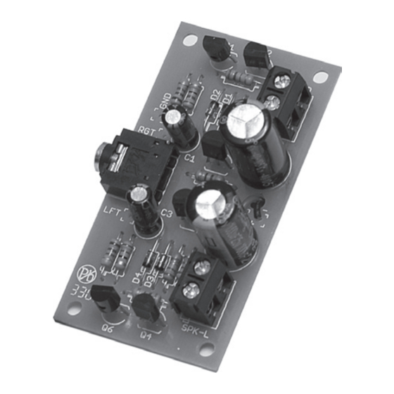
Low Power Audio Amplifier Kit
Code: 211-199
Resistors
To select the correct value, check the colour code in the
table below. Use a multimeter to check the resistance if
you are unsure (be careful when checking resistors more
than a few kilohms, as the resistance of your skin could
alter the reading).
�����
�
�����
�
���
�
������
�
������
�
�����
�
����
�
������
�
����
�
�����
�
Qty
Value
2
1.5 kΩ
4
2.2 Ω
2
5.6 kΩ
2
22 Ω
2
470 Ω
Diodes
Diodes need to be inserted the correct way around.
One end of the diode will have a stripe around the case,
match this end to the stripe show on the circuit board.
Anode
Qty
Value
4
1N4148
Capacitors
Electrolytic capacitors must be inserted the correct way
round. The longer leg is positive and should be inserted
into the hole marked with a + symbol on the circuit
board. The shorter negative leg is usually marked with a
stripe containing – symbols on that side of the capacitor.
Qty
Value
2
2.2 µF
2
1000 µF
���������
�����������
�
���������
��������
�
��������
�
�������������
�
��������������
�
��������������
�
���������������
�
�
��������
�����������������������
�
����������
�
Part Name
R2, R8
R5, R6, R11, R12
R1, R7
R3, R9
R4, R10
Cathode
Part Name
D1, D2, D3, D4
Negative
Part Name
C1, C3
C2, C4
Advertisement

Summary of Contents for Mindsets 211-199
- Page 1 Low Power Audio Amplifier Kit Code: 211-199 Resistors To select the correct value, check the colour code in the table below. Use a multimeter to check the resistance if you are unsure (be careful when checking resistors more than a few kilohms, as the resistance of your skin could alter the reading).
- Page 2 Pair of two-way screw terminals for left and right speakers. Wire a 4Ω or 8Ω speaker to each terminal block. Both left and right speakers should be the same type. cut the tracks where marked by the white lines Supplied by: Mindsets (UK) Ltd., Web: www.mindsetsonline.co.uk...
Need help?
Do you have a question about the 211-199 and is the answer not in the manual?
Questions and answers