Table of Contents
Advertisement
Quick Links
Advertisement
Table of Contents

Related Manuals for NIPROS PS270

Summary of Contents for NIPROS PS270
- Page 1 All manuals and user guides at all-guides.com PS270/570 Operating Instructions Before operating the system, please read this manual thoroughly and retain it for future reference. Volume 1.5, 1st edition Ver. 3.1 (serial number 735322 and Upper) ...
- Page 2 NIPROS/1 is class 1 laser product. (IEC60825-1+A2:2001) Do not directly look into the Optical fiber connector, since laser light is emitted from its tips.
- Page 3 All manuals and user guides at all-guides.com Optical Fiber Camera Adapter PS-270 PS-270 各部名称と働き Connector panel コネクタパネル GENLOCK output connector Output the Genlock reference signal to the camcorder. GENLOCK信号を出力するコネクタです。 REMOTE connector Connect with the remote control unit, SONY RM-B150,B750, and connect to the camcorder by the supplied 8-pin remote cable. ソニー社製RM-B150,750に適合するコネクタです。RCC-450(付属)を使ってカメラと接続します。 LANC connector Output the remote control signal to a SONY camcorder equipped with the LANC terminal (φ2.5 mini-jack). ソニー社製LANCリモコンに対応するリモコン用φ2.5ジャックです。 TC IN connector Connect the time code signal from the camcorder to synchronize with video equipment connected to the Optical Fiber Base Station PS-570. カメラのTC OUTから接続してPS-570に接続されたVTR等との同期を取るためのコネクタです。 TC OUT connector Output the time code signal to the camcorder from the Optical Fiber Base Station PS-570 to synchronize with video equipment connected to the Optical Fiber Base Station PS-570. カメラのTC INへ接続してPS-570に接続されたVTR等からのタイムコード信号により同期を取るためのコネクタです。...
-
Page 4: Names And Functions Of Parts
All manuals and user guides at all-guides.com Names and Functions of Parts Optical Fiber Base Station PS-570 PS-570 各部名称と働き Front panel 前面パネル HEADSET EXT LINE (4W I/O) INTERCOM POWER switch Turns the power on or off. 電源をON/OFFします。 Operation status indicator Shows the current system status. 光信号の通信状況を表示します。 HD : Lights up when the HD-SDI signal from the Optical Fiber Camera Adaptor PS-270 is received. LED OFF : When the SD-SDI signal is received. HD: HD-SDI信号がカメラアダプタから送られてきているとき点灯します。消灯の場合はSD-SDI信号が伝送されています。 LS : Lights up when the Laser signal from the Optical Fiber Camera Adaptor PS-270 is received. LS: レーザー信号がカメラアダプタから送られてきているとき点灯します。 INTERCOM EXT LINE 4W I/O ON/OFF switch Turns on or off the connection to the external 4-wire intercom line. 外部インターカム4Wラインへの接続をON/OFFします。... - Page 5 All manuals and user guides at all-guides.com Optical Fiber Camera Adapter PS-270 Front panel 前面パネル DC12 VOUT connector (XLR-4, female) Outputs DC12V power supplied from the Optical Fiber Base Station PS-570 for a camera light, a monitor, a prompter, and etc.(the maximum electric power is 30W) PS-570から供給される12V系電源を出力するキャノン4Pメス出力です。カメラ、カムライト、LCDモニター等の電源に 使用します。 MONITOR OUT connector Connect to the monitor by the supplied 6-pin cable. モニターにVF6Pケーブルを使って接続します。 TALLY indicator Lights up when receiving the tally signal from the Optical Fiber Base Station PS-570. The light can be turned on and off with the TALLY ON/OFF switch. PS-570からのタリー信号を受けて点灯します。タリーON/OFFスイッチにより任意に消灯させることができます。 TALLY ON/OFF switch Turns the TALLY indicator on and off. タリーLEDをON/OFFするスイッチです。...
-
Page 6: Rear Panel
All manuals and user guides at all-guides.com Optical Fiber Camera Adapter PS-270 Rear panel 背面パネル TALLY ON/OFF switch Turns on or off the TALLY indicator on the rear panel. リアパネルのタリー表示を任意に点灯/消灯するためのスイッチです。 TALLY indicator Lights up when receiving the tally signal from the Optical Fiber Base Station PS-570. It doesnʼt light up when the TALLY ON /OFF switch is turned off. PS-570からタリー信号を受けて点灯します。タリー表示ON/OFFスイッチをOFFにすると消灯したままになります。 Optical Cable connector Connects with the Optical Fiber Base Station PS-570 with an optical fiber cable. The maximum length of an optical fiber cable is 2000m. ベースステーションPS-570と光ケーブル(別売ALC-100M等)にて接続するコネクタです。最大2kmまで使用可能です。 INTERCOM HEADSET 2 TALK SWITCH connector When this connector is shorted, the microphone of intercom headset 2 operates. このコネクタをショートするとインカム2のマイクが動作します。 チップ MIC ON スリーブ... -
Page 7: Connector Panel
All manuals and user guides at all-guides.com Optical Fiber Camera Adapter PS-270 Connector panel コネクタパネル DC12V /INTERCOM HEADSET 1 connector Connect the supplied Intercom headset DL-400. Or connect the DC12V power supply for DC operation. インカムを使用する場合にヘッドセット (DL-400)を挿入するコネクタです。 DC12V電源を入力することが可能です。 MIC(G) INTERCOM HEADSET 2 connector MIC(H) Connects the supplied Intercom headset DL-400. H.PHONE(G) インカムを使用する場合にヘッドセット (DL-400)を挿入するコネクタです。 H.PHONE(H) In case using the headset with the XLR-4P Male connector, make and use the cable with the XLR-4P Female-Female connectors. キャノン4Pオスコネクタのヘッドセットを使用する場合は、 キャノン4Pメス-メスのケーブルを製作して使用して下さい。 DC OUT connector DC12V(G) Output DC 8.4V power to the camcorder and DC8.4V(G) DC12V power to a wireless receiver with the supplied DC cable. DC8.4V(+) DC12V(+) ハンディカメラ用8.4V及びワイヤレス用12Vを出力するコネクタです。 HD-SDI/SD-SDI input connector Connector to input the HD-SDI or SD-SDI output signal from the camcorder. HD-SDIまたはSD-SDI信号を入力するBNCコネクタです。... - Page 8 All manuals and user guides at all-guides.com Optical Fiber Camera Adapter PS-270 Connector panel コネクタパネル GENLOCK output connector Output the Genlock reference signal to the camcorder. GENLOCK信号を出力するコネクタです。 REMOTE connector Connect with the remote control unit, SONY RM-B150,B750, and connect to the camcorder by the supplied 8-pin remote cable. ソニー社製RM-B150,750に適合するコネクタです。RCC-450(付属)を使ってカメラと接続します。 LANC connector Output the remote control signal to a SONY camcorder equipped with the LANC terminal (φ2.5 mini-jack). ソニー社製LANCリモコンに対応するリモコン用φ2.5ジャックです。 TC IN connector Connect the time code signal from the camcorder to synchronize with video equipment connected to the Optical Fiber Base Station PS-570. カメラのTC OUTから接続してPS-570に接続されたVTR等との同期を取るためのコネクタです。 TC OUT connector Output the time code signal to the camcorder from the Optical Fiber Base Station PS-570 to synchronize with video equipment connected to the Optical Fiber Base Station PS-570. カメラのTC INへ接続してPS-570に接続されたVTR等からのタイムコード信号により同期を取るためのコネクタです。...
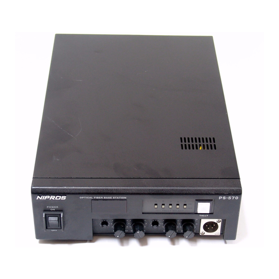
- Page 9 All manuals and user guides at all-guides.com Names and Functions of Parts Optical Fiber Base Station PS-570 Front panel 前面パネル HEADSET EXT LINE (4W I/O) INTERCOM POWER switch Turns the power on or off. 電源をON/OFFします。 Operation status indicator Shows the current system status. 光信号の通信状況を表示します。 HD : Lights up when the HD-SDI signal from the Optical Fiber Camera Adaptor PS-270 is received. LED OFF : When the SD-SDI signal is received. HD: HD-SDI信号がカメラアダプタから送られてきているとき点灯します。消灯の場合はSD-SDI信号が伝送されています。 LS : Lights up when the Laser signal from the Optical Fiber Camera Adaptor PS-270 is received. LS: レーザー信号がカメラアダプタから送られてきているとき点灯します。 INTERCOM EXT LINE 4W I/O ON/OFF switch Turns on or off the connection to the external 4-wire intercom line. 外部インターカム4Wラインへの接続をON/OFFします。...
- Page 10 All manuals and user guides at all-guides.com Optical Fiber Camera Adapter PS-270 PS-270 各部名称と働き Connector panel コネクタパネル DC12V /INTERCOM HEADSET 1 connector Connect the supplied Intercom headset DL-400. Or connect the DC12V power supply for DC operation. インカムを使用する場合にヘッドセット (DL-400)を挿入するコネクタです。 DC12V電源を入力することが可能です。 MIC(G) INTERCOM HEADSET 2 connector MIC(H) Connects the supplied Intercom headset DL-400. H.PHONE(G) インカムを使用する場合にヘッドセット (DL-400)を挿入するコネクタです。 H.PHONE(H) In case using the headset with the XLR-4P Male connector, make and use the cable with the XLR-4P Female-Female connectors. キャノン4Pオスコネクタのヘッドセットを使用する場合は、 キャノン4Pメス-メスのケーブルを製作して使用して下さい。 DC OUT connector DC12V(G) Output DC 8.4V power to the camcorder and DC8.4V(G) DC12V power to a wireless receiver with the supplied DC cable. DC8.4V(+) DC12V(+) ハンディカメラ用8.4V及びワイヤレス用12Vを出力するコネクタです。 HD-SDI/SD-SDI input connector Connector to input the HD-SDI or SD-SDI output signal from the camcorder.
-
Page 11: Rear Panel
All manuals and user guides at all-guides.com Optical Fiber Camera Adapter PS-270 PS-270 各部名称と働き Rear panel 背面パネル TALLY ON/OFF switch Turns on or off the TALLY indicator on the rear panel. リアパネルのタリー表示を任意に点灯/消灯するためのスイッチです。 TALLY indicator Lights up when receiving the tally signal from the Optical Fiber Base Station PS-570. It doesnʼt light up when the TALLY ON /OFF switch is turned off. PS-570からタリー信号を受けて点灯します。タリー表示ON/OFFスイッチをOFFにすると消灯したままになります。 Optical Cable connector Connects with the Optical Fiber Base Station PS-570 with an optical fiber cable. The maximum length of an optical fiber cable is 2000m. ベースステーションPS-570と光ケーブル(別売ALC-100M等)にて接続するコネクタです。最大2kmまで使用可能です。 INTERCOM HEADSET 2 TALK SWITCH connector When this connector is shorted, the microphone of intercom headset 2 operates. このコネクタをショートするとインカム2のマイクが動作します。 チップ MIC ON スリーブ... - Page 12 All manuals and user guides at all-guides.com Optical Fiber Camera Adapter PS-270 PS-270 各部名称と働き Front panel 前面パネル DC12 VOUT connector (XLR-4, female) Outputs DC12V power supplied from the Optical Fiber Base Station PS-570 for a camera light, a monitor, a prompter, and etc.(the maximum electric power is 30W) PS-570から供給される12V系電源を出力するキャノン4Pメス出力です。カメラ、カムライト、LCDモニター等の電源に 使用します。 MONITOR OUT connector Connect to the monitor by the supplied 6-pin cable. モニターにVF6Pケーブルを使って接続します。 TALLY indicator Lights up when receiving the tally signal from the Optical Fiber Base Station PS-570. The light can be turned on and off with the TALLY ON/OFF switch. PS-570からのタリー信号を受けて点灯します。タリーON/OFFスイッチにより任意に消灯させることができます。 TALLY ON/OFF switch Turns the TALLY indicator on and off. タリーLEDをON/OFFするスイッチです。...
- Page 13 All manuals and user guides at all-guides.com Names and Functions of Parts Optical Fiber Camera Adapter PS-270 PS-270 各部名称と働き Main panel メインパネル POWER switch Turns the power on and off. 電源をON/OFFするスイッチです。 POWER indicator Lights up when the power switch is on. 電源スイッチがONになっている時に点灯します。 TALLY indicator Lights up when receiving the tally signal from the Optical Fiber Base Station PS-570. PS-570からのタリー信号を受けて点灯します。 INCOM HEADSET 1 H.P and SIDE TONE volumes Adjusts the audio levels of the microphone and the headphone of the Intercom headset DL-400 connected to the HEADSET 1 connector (XLR-4P) on the rear panel. コネクタパネルのヘッドセットコネクタ1(XLR-4P,キャノン4P)に接続されたヘッドセットDL-400のHPレベルおよび SIDE TONEレベルを調整するボリュームです。 INCOM HEADSET 2 H.P and SIDE TONE volumes Adjusts the audio levels of the microphone and the headphone of the Intercom Headset DL-400 connected to the HEADSET 2 connector (XLR-4P) on the rear panel. コネクタパネルのヘッドセットコネクタ2(XLR-4P,キャノン4P)に接続されたヘッドセットDL-400のHPレベルおよび SIDE TONEレベルを調整するボリュームです。...
-
Page 14: Table Of Contents
All manuals and user guides at all-guides.com Table of contents Optical Fiber Studio System NIPROS LS−270 & LS−570 Names and Functions of Parts PS-270 Main panel Front panel Rear panel Connector panel PS-570 Front panel Rear panel LVM-89W/Universul Head System Connection Pre-adjustment and Setting System Connection Guide Multi-Camera System Connection Guide Outside View and Dimensions PS-270 PS-570 LVM-89W Specifications 仕様 PS-270 PS-570 LVM-89W... - Page 15 All manuals and user guides at all-guides.com HDMI/HD Component Monitor LVM-89W/Universal Head LVM-89W 各部名称と働き LVM-89W FRONT TALLY and REAR TALLY display select switch The brightness of the TALLY indicators on the front and rear panels can be selected by the select switches as follows. H : The tally indicator lights up brightly. L : The tally indicator is dimmed to the lower brightness. OFF : The tally indicator is turned off. フロントタリー、 リアタリーの明るさの切替 (OFF/L(low)/H(high)) スイ ッチです。 REAR GREEN TALLY indicator GREEN TALLY indicator on the rear panel lights up when the tally signal(2〜4V=GREEN) is input to the TALLY IN connector on the connector panel. The brightness of the indicator can be selected by the REAR TALLY display select switch. グリーンタリーは、 コネクタパネルのTALLY IN コネクタに入力されるタリー信号 (2〜4V=GREEN ON)により点灯します。 フロントパネルのリアタリー切替スイ ッチ(OFF/L(low)/H(high))で明るさの切替えが可能です。 REAR RED TALLY indicator RED TALLY indicator on the rear panel lights up when the tally signal(4〜 V=RED) is input to the TALLY IN connector on the connector panel or the tally signal(0V=ON, OPEN=OFF) is input to the MONI IF connector. The brightness of the indicator can be selected by the REAR TALLY select switch. レッドタリーは、 コネクタパネルのTALLY IN コネクタに入力されるタリー信号 (4V以上=RED ON)により点灯します。 また、 MONI IF コネクタに入力されるタリー信号(0V=ON)でも点灯します。 フロントパネルのリアタリー切替スイ...
- Page 16 All manuals and user guides at all-guides.com HDMI/HD Component Monitor LVM-89W/Universal Head LVM-89W各部名称と働き LVM-89W Function buttons PEAKING 16:9 MARKER COLOR INPUT MONO INPUT(入力セレクト)ボタンで、HD コンポーネントコネクタ、CMP IN コンポジット入力コネクタ, HDMI コネクタ に 接続された信号から入力する信号を選択します。INPUT ボタンを順次押して、選択します。 選択された入力モードが画面に表示されます。 INPUT select button mode(in sequence) signal : input connector (BNC) connector COMP 1 HD component : HD/Y, HD/B-Y, HD/R-Y CVBS 1 composite : CMP IN (BNC) connector COMP 2 CVBS 2 HDMI HDMI : HDMI connector PEAKING button : By pressing PEAKING button select the peaking function ON or OFF. When PEAKING is ON, the peaking level is adjustable by the MENU and -/+ button. PEAKING(ピーキング) ボタンで ON/OFF します。ON のとき、ピーキングレベルはメニューで調節できます。 16:9 / 4:3 button : By pressing 16:9/4:3 button, select the frame size 16:9 or 4:3. 16:9 / 4:3 ボタンで フレームサイズの切替えができます。 MARKER button : By pressing Marker button select the marker in sequence as follows. MARKER(マーカー) ボタンを押して順次マーカーサイズを切り替えます。 no marker 16:9 16:9 with cross marker 4:3 with cross marker...
- Page 17 All manuals and user guides at all-guides.com HDMI/HD Component Monitor LVM-89W/Universal Head LVM-89W各部名称と働き LVM-89W HD/Y, HD/B-Y, HD/R-Y connectors (BNC) Input HD component signals. The input signals are displayed when the input select mode is set to the “ COMP 1” mode. HD コンポーネント(HD/Y, HD/B-Y, HD/R-Y)信号を入力します。INPUT 切替ボタンをCOMP 1 に切り替えて表示します。 CMP IN connector (BNC) Input a composite video signal. The input signal is displayed when the input select mode is set to the “ CVBS 1” mode. コンポジットビデオ信号を入力します。INPUT 切替ボタンをCVBS 1 に切り替えて表示します。 In order to monitor the return video signal(composite) from the camera adaptor, connect the signal to this connector with BNC cable. ※カメラアダプターからのリターン信号(コンポジット)をモニターする場合は、リターン信号をこのコネクタに接続します。 CMP OUT connector (BNC) Outputs the composite video signal. (Through output of the CMP IN input signal) CMP IN コネクタに入力されたコンポジットビデオ信号をスルーで出力します。 TALLY IN connector (BNC) Input the tally signal( O〜2V=OFF, 2〜4V=GREEN, 4〜 V=RED ). タリー信号を入力します。タリー信号の電圧により、2〜4VのときGREEN, 4V以上のときREDが点灯します。 MONI IF connector (6-pin, female) MONI IF connector (6-pin, female) The DC 12V power and the tally signal are supplied from the Camera Pin assignment Adaptor via the supplied 6-pin cable(VC-450). カメラアダプタから付属の6ピンケーブルを通して、12V電源、タリー信号が入力されます。 +12V IN 約650mA For the use of the supplied 6-pin cable only. ※専用6ピンケーブルのみ使用可能です。 TALLY IN 0V=ON ...
- Page 18 All manuals and user guides at all-guides.com HDMI/HD Component Monitor LVM-89W/Universal Head LVM-89W 各部名称と働き Universal Head Monitor Lock Screw(1/4 inch) モニター固定ネジ Used to fix the monitor. Angle Adjustment Knob 角度調節ノブ Used to adjust the monitor position to any angle so that the display can be watch well. Slide-Shoe Lock Knob スライドシュー固定ノブ Used to fix the Slide Shoe to a camera accessory shoe. Slide-Shoe スライドシュー Slide into a camera accessory shoe. 1/4 inch Screw Hole 1/4インチネジ穴 Used to be fitted up with a 1/4 inch camera screw (male). When mounted on the camera with the 1/4 inch screw hole(female), install supplied 1/4 inch male-male screw adaptpr and fitted up with the camera. ...
-
Page 19: System Connection
All manuals and user guides at all-guides.com System Connection Optical Fiber Studio System NIPROS PS−270 & PS−570 Make sure the POWER switches of each unit are off before connection 接続する前に、 各機器の電源スイ ッチは必ず OFF にしてください。 Fix the PS-270 tightly to the bottom surface of the camcorder PMW-EX3 with the camera screw (w1/4). PMW-EX3の底面にPS-270 をカメラネジでしっかり締めて固定します。 PMW-EX3 PS-270 Fix the camcorder PMW-EX3 to a tripod. 三脚に装着します。 Fix the supplied universal head to the screw hole on the bottom surface of the monitor with the Monitor Lock Screw. モニター下部の1/4インチ固定ネジ穴にモニター固定ネジで固定します。 monitor Bottom Monitor Lock Screw Universal head... - Page 20 All manuals and user guides at all-guides.com System Connection NIPROS PS−570 Slide the monitor to the stop position of the accessory shoe of PMW-EX3. Tighten the Slide-Shoe Lock Knob to fix the monitor. Loosen the Angle Adjustment Knob and adjust the angle of the monitor so that the monitor can be watched easily, then tighten the knob again. カメラのアクセサリーシューの止まる位置までスライドさせます。 シューから抜けないようにシュー固定ねじで固定します。 角度調整固定ねじを緩めてモニターの見やすい位置が決まった後、再度固定ねじを締めます。 Angle Adjustment Knob Slide-Shoe Lock Knob Slide-Shoe Accessory Shoe Connect the MONITOR OUT connector of PS-270 to the MONI IF connector of the monitor with the supplied 6-pin cable (VC-450) and connect the RET connector to the CMP IN connector with a BNC cable. PS-270とモニターLVM-89Wを6Pケーブル(VC-450) とBNCケーブルで接続します。 monitor LVM-89W HD/Y HD/B-Y HD/R-Y CMP IN BNC cable CMP IN CMP OUT TALLY IN MONI IF MONI IF supplied 6-pin cable (VC-450) DC 12V IN RET MONITOR OUT...
- Page 21 All manuals and user guides at all-guides.com System Connection NIPROS PLS−570 Connect the HD-SDI/ SD-SDI input connector with the HD-SDI output connector of the camcorder by a BNC cable PS-270のHD-SDI/SD-SDIコネクタへカメラのHD-SDI/SD-SDI出力からBNCケーブルで接続します。 PS-270 HD-SDI/SD-SDI HD-SDI/SD-SDI input connector output connector In case of using Genlock reference signal, connect the GENLOCK output connector to the input connector of the camcorder by a BNC cable. PS-270のGENLOCKコネクタからカメラのGENLOCK INへBNCケーブルで接続します。 PS-270 GENLOCK GENLOCK input connector output connector In case of using Time Code (TC) signal, connect the TC IN or OUT connector with of the camcorder by a BNC cable. PS-270のTC IN または TC OUTコネクタとカメラのTC OUT または INコネクタとをBNCケーブルで接続します。 TC IN TC OUT connector connector PS-270 TC IN TC OUT TC signal from VTR, etc. TC signal from Camcorder...
- Page 22 All manuals and user guides at all-guides.com System Connection NIPROS PS−570 Connect the REMOTE connector to the camcorder by the supplied 8-pin remote cable. PS-270のREMOTEコネクタからカメラのREMOTE端子へ専用8Pケーブル(RCC-450)で接続します。 REMOTE connector PS-270 8Pケーブル(RCC-450) Connect the DC OUT connector to the DC IN connector of the camcorder by the supplied DC cable. PS-270のDC OUTコネクタからカメラのDC INコネクタへDCケーブル(DC-EX3)で接続します。 DC OUT connector PS-270 DCケーブル(DC-EX3) DC input connector Connect the supplied Intercom headset DL-400 to the HEADSET connector. ヘッドセット(DL-400)をヘッドセットコネクタに接続します。 PS-270 DL-400 INCOM HEADSET connector...
- Page 23 All manuals and user guides at all-guides.com System Connection NIPROS PS−570 Connect the HD-SDI/SD-SDI OUT connector to a switcher, a monitor or a video recording equipment by a BNC cable. PS-570のHD-SDI/SDI OUTコネクタからスイッチャー、レコーダーもしくはモニターへBNCケーブルで接続します。 PS-570 to switcher, HD-SDI/SDI OUT connector monitor, VTR, etc. Connect the RET IN connector with a switcher to input the return video signal(composite) by a BNC cable. RET INコネクタにRET信号(コンポジット信号)をBNCケーブルで接続します。 PS-57 RET IN connector from switcher, etc. In case of using a Genlock reference signal, connect a Genlock reference signal to the GENLOCK connector by a BNC cable. GENLOCK INコネクタへGENLOCK信号(コンポジット信号)をBNCケーブルで接続します。 PS-570 GENLOCK connector...
- Page 24 All manuals and user guides at all-guides.com System Connection NIPROS PS−570 Connect the the SONY remote controller to the REMOTE connector by the supplied 8-pin remote cable. リモコンを使用するときはREMOTEコネクタへソニー社製のリモコンをリモコンに付属しているケーブルにて接続します。 PS-570 REMOTE connector In case of the multi-camera operation, connect the INCOM connector with the INCOM connector of other PS-570 by a BNC cable. INCOMを他のPS-570と接続する場合はINCOMコネクタにBNCケーブルを接続します。 PS-570 INCOM connector Connect the tally output signals from a switcher to the TALLY IN connector by the supplied multi cable. In case of multi-camera operation, connect the TALLY OUT connector to the TALLY IN connector of other PS-570 by the 15P multi cable. タリー表示を行う場合はTALLY INにスイッチャー等からの信号を接続します。 複数台のPS-570を接続する場合は、TALLY OUTから他のPS-570へ15P-15Pケーブルで接続します。 From a switcher or To other PS-570 other PS-570 TALLY IN/OUT connector PS-570...
- Page 25 All manuals and user guides at all-guides.com System Connection NIPROS PS−570 In case of using Time Code, connect the TC IN/OUT connector to the time code out/in of an external recording equipment. TC INにVTR等のTC OUT信号を、TC OUTにVTR等のTC IN信号を接続します。 PS-570 TC IN/OUT connector Connect an external 2 wire intercom line to the INCOM 2W connector. Connect an external 4 wire intercom line to the AUX/INCOM 4W connector. 外部2W インカムシステムと通話する場合XLR 3Sに接続します。 4W INCOMシステムと通話する場合はXLR-5Sと接続します。 PS-570 INCOM 2W connector AUX/INCOM 4W connector Connect the supplied AC power cable to the AC in connector. For DC operation, connect an optional DC power supply to the DC12V IN connector. AC電源ケーブルを接続します。またはDC 12V IN コネクタにDC電源を接続します。 DC12V IN connector PS-570 AC IN connector...
- Page 26 All manuals and user guides at all-guides.com System Connection NIPROS PS−570 Connect the Intercom headset DL-400 to the INCOM (Intercom headset) connector インカムコネクタにヘッドセット(DL-400)を接続します。 HEADSET EXT LINE (4W I/O) INTERCOM INCOM connector DL-400...
- Page 27 All manuals and user guides at all-guides.com System Connection NIPROS PS−570 Connect an optional Optical fiber cable to the OPT CABLE connector of PS-270. PS-270コネクタパネルの光ケーブルコネクタからPS-570へ光ケーブル(別売AC-100M)を接続します。 PS-270 OPT Cable connector Connect the OPT CABLE connector of PS-570 with an optional Optical fiber cable from PS-270. PS570のOPTケーブルコネクタにカメラアダプタPS-270から光ケーブル(別売ALC-100M,他)を接続します。 PS-570 OPT cable connector...
-
Page 28: Pre-Adjustment And Setting
All manuals and user guides at all-guides.com Pre-Adjustment and setting Optical Fiber Studio System NIPROS PS−270 & PS−570 Turn on the power switches of PS-270,PS-570 and PMW-EX3 Make sure the volume of each unit is set to the minimum position before starting adjustment. Never turn up the volumes suddenly to prevent hearing impairment. ※電源スイッチをONにする前にヘッドセットのボリュームを最小の位置にして下さい。 Adjust intercom volume level PS-270 SIDE TONE SIDE TONE DL-400 Volume Put on the Intercom headset DL-400 インカムヘッドセットDL-400を装着します。 While listening to the operlator, turn up the H.P volume gradually so that you can hear the voice clearly. H.P. を徐々に上げていきます。 相手の声がよく聞こえるように、 接続されたヘッドセット側の H.P ボリュームを調整します。 Turn up or down the SIDE TONE volume. 自分の声をSIDE TONEで調整します。... - Page 29 All manuals and user guides at all-guides.com Pre-Adjustment and Setting NIPROS PS−570 PS-570 HEADSET EXT LINE (4W I/O) INTERCOM DL-400 Volume Volume Put on the Intercom headset DL-400 インカムヘッドセットDL-400を装着します。 While listening your voice and the cameramanʼs, turn up the MIC volume and H.P volume gradually so that you can hear both voices clearly. Turn down the SIDE TONE volume slightly. H.P.とMICボリュームを徐々に上げていきます。相手の声と自分のMICの声がよく聞こえるように接続されたヘッドセット側の 2つのボリュームを調整します。 When connecting to an external 4-wire intercom system, turn on the 4W I/O ON/OFF switch and adjust the AUX input/output level by the EXT LINE volumes. 4ワイヤーインカムシステムに接続する場合は、4W I/O スイッチをONにして、EXT LINE ボリュームでAUX/INCOM 4W のインプット/アウトプット/サイドトーンを調整します。...
- Page 30 All manuals and user guides at all-guides.com Pre-Adjustment and Setting NIPROS PS−570 Setting Select Tally indication channels of PS-570 with TALLY SELECT switches. Make sure the TALLY indicator lights up correctly when the corresponding tally channels of a switcher are selected. PS-570の前面パネルにあるスイッチをタリー選択時に点灯するように設定したいチャンネルのみONにします。 Set the switch(s) to ON to light up the TALLY indicator(s) of selected channel(s). 選択するCHをONにします。 Now that the pre-adjustment and setting are done, ensure Camera pictures and RET signal are displayed properly and tally indicators of PS-270 and the monitor are light up. If itʼs OK, the multi-camera system is ready to start recording. This camera adaptor system is specially designed for a SONY camcorder. Never use a camcorder made by the other manufactures. If you use, the system might not perform as expected or damage the camera.
-
Page 31: System Connection Guide
All manuals and user guides at all-guides.com System Connection Guide Optical Fiber Studio System NIPROS PS−270 & PS−570 NIPROS PS−270/570 OPTICAL FIBER STUDIO SYSTEM CLASS 1 LASER PRODUCT System Connection Guide CMP IN コンポジット イン Supplied Accessories MONITOR LVM-89W 1 PEAKING 16:9 MARKER COLOR INPUT UNIVERSAL HEAD 1 MONO MONITOR HEAD SET DL-400 2 MONITOR IF モニター... -
Page 32: Multi-Camera System Connection Guide
All manuals and user guides at all-guides.com Multi-Camera System Connection Guide Optical Fiber Studio System NIPROS PS−270 & PS−570 ●Camera 1 ●Monitor ●BNC cable ●Headset DL-400 ●6-Pin cable Tally/Return/Genlock VC-450 Switcher PEAKING 16:9 MARKER COLOR INPUT MONO ●PMW-EX3 HD-SDI 2/SD-SDI ●HD-SDI cable ( BNC) ●Rack Mount kit HS-RA90 ●Gen Lock cable ( BNC)... -
Page 33: Outside View And Dimensions
All manuals and user guides at all-guides.com Outside View and Dimensions Optical Fiber Camera Adapter PS-270 (front) (rear) (connector panel) Outside dimension (unit: mm) 外形寸法図 (単位: ミリ)... - Page 34 All manuals and user guides at all-guides.com Outside View and Dimensions Optical Fiber Base Station PS-570 EXT LINE (4W I/O) INTERCOM HEADSET (rear) Outside dimension (unit: mm) 外形寸法図 (単位: ミリ)...
- Page 35 All manuals and user guides at all-guides.com Outside View and Dimensions HDMI/HD Component Monitor LVM-89W/Universal Head 217mm HD/Y HD/B-Y HD/R-Y CMP IN CMP OUT TALLY IN MONI IF PEAKING 16:9 MARKER COLOR INPUT DC 12V IN MONO Outside dimension (unit: mm) 外形寸法図 (単位: ミリ)...
- Page 36 All manuals and user guides at all-guides.com Specifications Optical Fiber Camera Adapter PS-270 Output Time Code BNC x1 Return BNC x1: 1Vp-p, 75Ω, Anaglog composite or HD-Y ※1 Genlock (Prompter) BNC x1: 1Vp-p, 75Ω, self-detecting, dual purpose Genlock/Teleprompter output, composite or HD-Y (down grade compared to standard HD signal) DC out XLR 4pin(female) x1: 13.5V 3.5A (Maximum 13.7V, 3.5A) Total 50W ※2 Mini 4pin(female) x1: DC 8.4V (Maximum 8.7V)or DC12V(Maximum 13.7V) Monitor Mini 6pin(female) x1: 13.5V 150mA (Maximum 13.7V), for Monitor Input DC In XLR 4pin(male) x1: 12V ※3 HD/SD- SDI HD-SDI :1.485Gbps,1.485/1.001Gbps(reclock) SD-SDI :143Mbps,177Mbps, 270Mbpd,460Mbps, 540Mbps(reclock) Incom Incom XLR 4pin(male) x2 MIC2ON mini-jach φ3.5mm Tally Tally ramp x3 Front x1 and Backx1 (Both On/Off Selectable), Right side x1 Remote Remote 8pin ※4 LANC Stereo mini-jack Φ2.5mm Optical fiber connection...
- Page 37 All manuals and user guides at all-guides.com Specifications Optical Fiber Base Station PS-570 Output HD/SD-SDI BNCx2: Audio,T/C embedded Tally D-sub 15pin x1 Time Code OUT BNC x1 Headset XLR 4 pin x1 Input Return signal BNCx1: Composite or HD-Y Time Code IN BNC x1: Genlock ※1 BNCx1: Composite or HD-Y Tally D-sub 15pin x1 XLR 4pin(male)x1: DC 12V Incom Incom XLR 3pin x1: 2W for Clearcom XLR 5pin x1: 4W Incom, IN:-10db to +4dB,OUT:-10dB BNC x1 Remote Remote 8pin ※2 LANC Stereo mini-jack Φ2.5mm Optical fiber connection Cable Plug LEMO P/N: FXW.3K.93C.TLM maximum distance 2km with power supplied via fiber optic cable to PS-270...
-
Page 38: Lvm-89W
All manuals and user guides at all-guides.com Specifications HDMI/HD Component Monitor LVM-89W/Universal Head LVM-89W Size 画面サイズ 8.9 inch-type 8.9 inches : Viewable area measured diagonally ( 196(H) x 115(V) mm ) Resolution 解像度 Effective Pixels 1024(H) x 600(V) x 3(RGB) 入力 Input XLR 4-pin (male) BNC x1: 1Vp-p, 75Ω (NTSC/PAL/SECAM auto detective) VBS(Composite) IN (HD/Y, HD/B-Y, HD/R-Y) HD Component IN BNC x3 : 1Vp-p, 75Ω Monitor I/F Mini 6-pin x1 (DC IN, TALLY IN) HDMI x1 (HDMI signal input) HDMI Tally IN BNC x1 : DC 2〜4V=GREEN, DC 4〜 V=RED (Front and Rear, Both OFF/L/H Selectable) Output 出力 VBS(Composite) OUT BNC x1: 1Vp-p, 75Ω Front 2 (GREEN and RED), Rear 2 (GREEN and RED) (Both OFF/L/H Selectable) Tally indicator ... - Page 39 All manuals and user guides at all-guides.com PS-270 / PS-570 Operating Instructions...
Need help?
Do you have a question about the PS270 and is the answer not in the manual?
Questions and answers