Advertisement
Quick Links
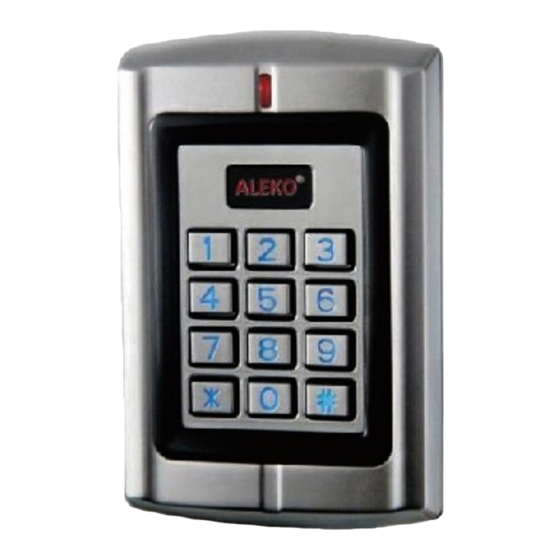
Wat er pr oof
Du al -r el ay Ac c ess Con t r ol
LM178
User M anual
www.AlekoProducts.com
sales@alekoproducts.com
1. Pac k i ng L i st
Name
Digital Keypad LM178
User Manual
Screw Driver
Rubber Bungs
Self Tapping Screws
Please ensure that all the above contents are correct. If any are
missing please notify the supplier of the LM178.
2. Desc r i pt i on
(
are in the same function, only different in shape. )
LM178
The
is a two relays multifunction standalone
LM177/LM178
access controller. It is suitable for mounting either indoor or
outdoor in harsh environments. It is housed in a strong,
sturdy and vandal proof zinc alloy electroplated case. The
electronics are fully potted so the
and conforms to IP68.
It supports up to 1200 users in either a Card, PIN, or a Card +
PIN option. The built-in card reader supports 125KHz EM
frequency card, and the PIN length is 4-8 digits.
Both of the two relays on board can operate in Pulse Mode
(suitable for access control) or Toggle Mode (suitable for arming/
disarming alarms, switching lights, machines....etc)
W1-A/W3-A is an ideal choice for door access not only for
small shops and domestic households but also for
commercial and industrial applications such as factories,
warehouses, laboratories, banks and prisons.
3. Feat ur es
> Waterproof, conforms to IP68
> S trong zinc alloy electroplated anti- vandal case
> Two- relay operation
> B oth of the 2 relays can be programmed for 3 m odes:
Card, PIN, Card + P IN
> 1 200 users
> Z one 1: up to 1100 PIN & Card holders
> Z one 2: up to 100 PIN & Card holders
Remark
Quantity
1
1
1
6*27mm, used for fixing
4
3.5*27mm, used for fixing
4
is waterproof
LM178
Advertisement

Summary of Contents for Aleko LM178
- Page 1 3.5*27mm, used for fixing Please ensure that all the above contents are correct. If any are missing please notify the supplier of the LM178. 2. Desc r i pt i on are in the same function, only different in shape. )
-
Page 2: Specifications
Blue& Black Electric Lock, Exit Button, Wiring Connections DOTL, Ext er nal Al ar m White&Black COM2 Green& Black Dimensions L128x W82 x H28 mm ( LM178 ) Blue Net Weight 650 g White COM1 Gross Weight 800 g Green... -
Page 3: Connection Diagram
AS & GateGuard Series Connection Diagram Power 12-24V DC/12-18V AC/5A LM178 Grey&Black GND FUNC ALARM Grey LEARN Request to Exit Button of Zone 2 Alarm o l l & + MOTOR1 - ULT1 COM DLT1 + MOTOR2 - ULT2 COM DLT2... - Page 4 AC2700, AR2750 AC1300,AR1350,AC2200,AR2250 - MOTOR + LL COM RL - LAMP + PHOTOCELL PUSHBUTTON LOCK LOOP - 24VDC OUT + - BAT + Grey&Black GND Grey&Black GND ALARM Grey ALARM Grey o l l & o l l & Yellow OPEN1 Yellow OPEN1 Brown D_IN Brown D_IN...
- Page 5 To reset to factory default, power off, press * , hold it and ses a LDR (light dependent resistor) as LM178 power on, release it until hear three beeps(two short, one an anti tamper alarm. If the keypad is removed from the long), means reset to factory default successfully.
- Page 6 0 New code # New code # To change the master code The master code is any 6 digits Setting the w orking m ode: , Zone 1 , Zone 2 Set valid Card or PIN users Entry is by either card or PIN (Factory default setting) , Zone 1 Set valid Card and PIN users , Zone 2...
- Page 7 To add a card user (Method 2) This is the alternative way to enter cards using user ID 1 User ID number # Card # allocation. In this method a user ID is allocated to a card. The ID number can be any number between 1-1100 Only one user ID can be allocated to a single card 5 User ID number # 8 digits Card number # Card quantity # To add a series cards users-Block Enrollment...
- Page 8 To change a PIN in card and PIN mode (Method 1) Note that this is done outside programming mode so the user can undertake this themselves To change a PIN in card and PIN mode (Method 2) Note that this is done outside programming mode so the user can undertake this themselves To delete a Card and PIN user just delete the card Read card...
-
Page 9: Toggle Mode
Toggle mode For Zone 1: 4 1 0 # Toggle mode For Zone 2: 4 2 0 # 11.3 Door D et ect i on, Al ar m , Acoust i c Si gnal , Door B el l Set t i ngs Door Open Detection Door Open Too Long (DOTL) warning. - Page 10 To enable the keypad tone 8 6 # ( Factory default setting) To disable keypad tone Change Zone 2 to Door Bell When no need to operate a second door, Zone 2 can be set to operate the Door Bell. The wiring is connecting the door bell to COM2 and NO2.
- Page 11 LM178 Qui c k R ef er enc e Pr ogr am m i ng Gui de * M aster code # To enter the programming mode 888888 is the default factory master code To exit from the programming mode...
Need help?
Do you have a question about the LM178 and is the answer not in the manual?
Questions and answers