Table of Contents
Advertisement
Quick Links
Advertisement
Table of Contents

Summary of Contents for HAWEKA SAD500
- Page 1 Operating manual Optical Adjustment System for ADAS (Advanced Driver Assistance Systems) (Translation of the original manual) Kokenhorststrasse 4 • 30938 Burgwedel (Germany) • Tel. +49 5139 8996-0 • Fax +49 5139 8996-222 www.haweka.com • info@haweka.com GEB 001 182...
-
Page 3: Table Of Contents
Optical Adjustment System SAD500 Table of Contents General Safety Instructions..................2 ’ ..................2 PERATOR S DUTY OF CARE ..................2 XPLANATION OF SYMBOLS ................... 3 ASIC SAFETY PRECAUTIONS Product Description ....................4 ..................5 UTHORISED INTENDED USE ....................5 ECHNICAL Equipment......................... -
Page 4: General Safety Instructions
SAD500 (referred to in the following only as SAD500) is only used as determined • the SAD500 is only used in a fully functioning state and free from defects • the complete operating instructions are permanently available in a readable condition at the operating location of the device •... -
Page 5: Basic Safety Precautions
Optical Adjustment System SAD500 Basic safety precautions Prior to each use of the SAD500, it must be checked for visible damage and it must be ensured that the system is only operated when free from defects! Any defects that are... -
Page 6: Product Description
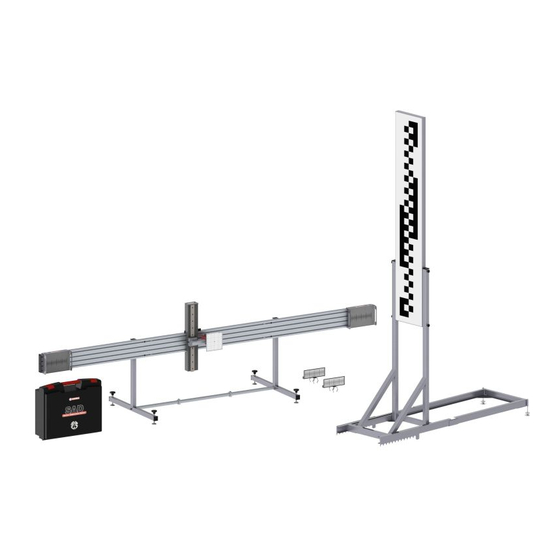
Optical Adjustment System SAD500 2 Product Description Optical Adjustment System SAD500 Item No. 922 000 013 Subject to technical modifications. 3. version 09/2017 Figures: HAWEKA AG / D-30938 Burgwedel Reproduction in any form is not permitted. SAD500... -
Page 7: Authorised Intended Use
Optical Adjustment System SAD500 Authorised intended use • The SAD500 has been developed in order to be able to carry out a check and for the adjustment of an Adaptive Cruise Control sensor (ACC sensor) on commercial vehicles. • The SAD500 is an additional module that, in combination with the wheel alignment system AXIS500, is used to measure the ACC sensor and for aligning the calibration panel for multi- function cameras of drive assist systems (ADAS). -
Page 8: Equipment
Optical Adjustment System SAD500 3 Equipment Parts list for SAD500 2 × scales with gripping jaws for laser measuring heads 2 × item no. 913 012 009 2 × mirrors (included in the item “measuring crosshead”) Mirror left 1 × item no. 913 051 025... -
Page 9: Optional Accessories For Sad500
Optical Adjustment System SAD500 1 × crosshead (incl. mirrors) 1 × item no. 922 001 015 1 × device storage case 1 × item no. 900e008 383 1 × operating Instructions 1 × item no. GEB 001 182 1 × CD Rom (measurement protocol + operating manual) 1 ×... -
Page 10: Preparatory Measures
Optical Adjustment System SAD500 4 Preparatory measures Assembly of the crosshead (Fig.1) The crosshead consists of: 2 device supports, 1 central part, 2 side elements (left and right), 2 mirrors, 1 receiving bars, 1 carriage and laser with scale. Step 1: Assembly of the slide rails. - Page 11 Optical Adjustment System SAD500 Step 2: (Fig. 3) 1.) Insert the fixing screws into the holes in the central part. 2.) Slide the side part with the centring pins into the central part until the pins are seated in the fixing screws.
- Page 12 Optical Adjustment System SAD500 Place the laser carriage on the slide rail of the crosshead from the front and set it into the guide groove. (Fig.5) (Fig.5) Slightly release the fixing screw on the laser housing and pull upwards. Place the laser housing on the pin on the...
-
Page 13: Setting Up Laser Measuring Heads And Scales
Optical Adjustment System SAD500 Setting up laser measuring heads and scales The wheel alignment clamps have to be converted for the rear wheels using the long magnetic feet (310 mm). (Fig. 8) • Place a scale on the measuring column of the wheel alignment clamp with the clamping jaws. -
Page 14: Aligning Crosshead With The Vehicle
Optical Adjustment System SAD500 Aligning crosshead with the vehicle The crosshead must be installed in the centre in front of the vehicle and parallel to the rear driving axle. Make sure that the laser with the measuring scale is positioned at the same height on the vehicle as the (Fig. - Page 15 Optical Adjustment System SAD500 • The horizontal alignment of the crosshead on the laser housing must be checked using the level I , readjust if required. • The crosshead can be aligned horizontally with the setting screws. (Fig. 16) Level I •...
-
Page 16: Measuring And Adjusting The Acc Sensor
Optical Adjustment System SAD500 5 Measuring and adjusting the ACC sensor Measuring the ACC sensor with reference mirror • The crosshead is aligned and is in the centre in front of the vehicle and parallel to the vehicle driving axle. -
Page 17: Measuring The Acc Sensor Without Reference Mirror
Optical Adjustment System SAD500 Measuring the ACC sensor without reference mirror For checking an ACC sensor without reference mirror (Fig. 21) the optional adapter mirror 922 001 011 must be (Fig. 20) mounted in front of the ACC sensor on the vehicle before the check. -
Page 18: Calibration Reflector For The Lane-Keeping Assistant
Optical Adjustment System SAD500 6 Calibration Reflector for the Lane-Keeping Assistant Assembly of the calibration reflector (Fig. 26) Step 1: Using 4 star grip screws M6 x 60, attach the reflector panel to the stand. Step 2: Insert the stand, with the reflector panel, into the base frame. -
Page 19: Setting The Calibration Reflector
Optical Adjustment System SAD500 Setting the calibration reflector Aligning the position: Before the lane-keeping camera of the vehicle is put in position, the calibration reflector must be at a distance specified by the vehicle manufacturers. • For this, the base frame of the calibration reflector is hung into the central rod of the previously aligned crosshead. - Page 20 Optical Adjustment System SAD500 Aligning horizontally: Subsequently, the reflector panel must be aligned into a horizontal position. • For this, the reflector stand is put into the rear position until the magnets rest on the base frame. (Fig. 31) (Fig. 31) There is a spirit level located on the rear of the reflector.
-
Page 21: Servicing
Optical Adjustment System SAD500 7 Servicing Maintenance and Care Please note that the laser measuring heads including the scales and wheel alignment clamps with their accessories are precision components. These components must be used and maintained with great care at all times. -
Page 22: Error Description
Optical Adjustment System SAD500 8 Error description Operators may only redress errors that are clearly the result of operating or maintenance errors! Description and causes of errors Description Possible causes Troubleshooting The laser beam becomes There is insufficient battery Turn off the system! -
Page 23: Ec Declaration Of Conformity
Optical Adjustment System SAD500 9 EC Declaration of Conformity HAWEKA AG The manufacturer: Kokenhorststr. 4 D-30938 Burgwedel Germany herewith declares that the following described system: Optical Adjustment System SAD500 Item number: 922 000 013 conforms to the requirements of the following directive:... -
Page 24: Haweka Ag
HAWEKA AG Kokenhorststr. 4 30938 Burgwedel +49 5139-8996- 0 +49 5139-8996-222 www.haweka.com Info@haweka.com...
Need help?
Do you have a question about the SAD500 and is the answer not in the manual?
Questions and answers