Tektronix 7A42 Operator's Manual
Logic triggered vertical amplifier
Hide thumbs
Also See for 7A42:
- Instruction manual (320 pages) ,
- Operator's manual (134 pages) ,
- Instruction manual (84 pages)

Related Manuals for Tektronix 7A42


Summary of Contents for Tektronix 7A42
- Page 1 O ERATORS RODUCT GROU MANUAL 070-4285-00 7A42 Logic Triggered Vertical Amplifier lease check for change information at the rear of this manual. First rinting A RIL 1983 ektronix Revised JUL 1984 COMMI ED O EXCELLENCE...
- Page 2 SERVICE MANUAL ................. 1-1 INSTALLATION ................... 1-2 INITIAL INS ECTION ................1-2 O ERATING TEM ERATURE ............1-3 INSTALLING THE 7A42 IN THE MAINFRAME ......... 1-3 MAINFRAME COM ATIBILITY ............1-4 ACKAGING FOR SHI MENT ............1-5 S ECIFICATION ....................1-6 STANDARD ACCESSORIES ..............
- Page 3 CLEAR ..................2-67 NOT ....................2-67 EDGE .................... 2-67 APPLICA IONS LICATION 1 — DIS LAYING FOUR CHANNELS OF DATA WITH THE 7A42 ..................3-1 MEASUREMENT TECHNIQUE ............3-1 VIEWING THE MASTER CLOCK LINE ........3-2 LICATION 2 — SOLVING ABNORMAL ULSE ROBLEMS WITH THE 7A42 ..................
- Page 4 HIGH S EED LOGIC SYSTEMS ............3-14 ROBING ECL CIRCUITS ............... 3-15 7A42 ROBE OFFSET FEATURE ........... 3-16 LICATION 7 — USING THE 7A42 WITH THE 7854 ...... 3-17 LICATION 8 — USING THE 7A42 WITH THE 7104 ...... 3-18 INS RUMEN OP IONS...
- Page 5 Triggering on a low-amplitude pulse ............3-5 Timing diagram of a typical microprocessor read cycle ....... 3-6 Set up to monitor invalid data transitions ..........3-8 The 7A42 captures a positive transition of data during the time data > should be stable ..................3-8 Bus contention measurement set up ..........
- Page 6 Electrical Characteristics ................1-6 Environmental Characteristics .............. 1-21 1- 4 hysical Characteristics ................. 1-22 2- 1 7A42 Self-Test Failure Messages ............2-51 7A42 Front- anel Control Settings When Initialized ......2-53 7A42 Operator Message Summary ............2-55 Channel Volts/Division Ranges ............2-65...
- Page 7 7A42 Operators OPERA ORS SAFE Y SUMMARY The general safety information in this part of the summary is for both operating and sevicing personnel. Specific warnings and cautions will be found throughout the manual where they apply, but may not appear in this summary.
- Page 8 7A42 Operators WARNINGS POWER SOURCE This product is intended to operate in a mainframe connected to a power source that will not apply more than 250 volts rms between the supply conductors or between either supply conductor and ground. A protective ground connection by way of the grounding conductor in the mainframe power cord is essential for safe operation.
- Page 9 TTL, ECL and CMOS logic families. While the display output from the 7A42 is analog, the trigger output is digital and is comprised of a user selectable Boolean function of the four input channels.
- Page 10 SECTION ONE GENERAL INFORMATION Shown above is the Tektronix 7A42, 7A13, and 7B92A installed in a Tektronix 7904A Oscilloscope. The 7904A is a general purpose, real-time 7000-series mainframe, featuring a 300 MHz system bandwidth with the 7A42.
- Page 11 SERVICE MANUAL ..................1-1 INSTALLATION ...................... 1-2 INITIAL INS ECTION ..................1-2 O ERATING TEM ERATURE ............... 1-3 INSTALLING THE 7A42 IN THE MAINFRAME ......... 1-3 MAINFRAME COM ATIBILITY ..............1-4 ACKAGING FOR SHI MENT ..............1-5 S ECIFICATION ......................1-6 STANDARD ACCESSORIES .................
- Page 12 Red, green and yellow color is used in this manual to visually correlate the front panel indicators and markings to the descriptions of the text. ECHNICAL MANUALS An operators and two service manuals are supplied with your 7A42 as standard accessories. The following information outlines the content of these manuals. Operators Manual The Operators Manual is divided into the following four sections: Section 1 —...
- Page 13 Get-Acquainted Exercises in Section 2, Operating Instructions. Qualified service personnel can verify erformance Requirements by referring to the Checks and Adjustment section of the service manual. If there is damage or deficiency, contact your local Tektronix Field Office or representative.
- Page 14 To install the 7A42 in the mainframe, align the grooves in the top and bottom of the instrument with the guides at the top and bottom of the plug-in compartment. Then push the 7A42 in until its front panel is flush with the front panel of the mainframe.
- Page 15 Chop has been selected as the Horizontal Mode, and if exactly four traces are to be displayed by the 7A42, two of the traces may synchronize to one time base while the other two traces synchronize to the other time base. To prevent this from happening, one trace should be removed, or a fifth trace should be added to the mainframe ert display (even if it is positioned off screen so it cannot be seen).
- Page 16 NO E Packa e and ship Plu -Ins and Mainframes separately. If this instrument is to be shipped to a Tektronix Service Center for service or repair, attach a tag to the instrument showing the following: Owner of the instrument (with address), the name of a person at your firm who can be contacted, complete instrument type and serial number, and a description of the service required.
- Page 17 General Information — 7A42 S ECIFICATION The electrical characteristics listed in Table 1-2 apply when the following conditions are met: (1) Adjustment of the instrument must have taken place at an ambient temperature between +20° and +30° C, (2) the instrument is allowed a 20- minute warm-up period, (3) specifications are valid at an ambient temperature of 0°...
- Page 18 General Information — 7A42 ABLE 1-2 (CON ) Electrical Characteristics Supplemental Characteristic Performance Requirement Information DISPLAY (CON ) Deflection Factor (cont) Gain Ratio Accuracy Within 2% of indi within the same cated deflection Channel factor relative to ECL Logic Family, 20 mV/div, 1 Megohm input impedance.
- Page 19 General Information — 7A42 ABLE 1-2 (CON ) Electrical Characteristics Characteristic Performance Supplemental Information Requirement DISPLAY (CON ) Maximum Input Voltage 25 V ( DC + peak AC ) 1 Megohm 36 MHz or less, derated linearly to 3 V (peak ac) at 300 Mhz.
- Page 20 General Information — 7A42 ABLE 1-2 (CON ) Electrical Characteristics Supplemental Performance Characteristic Information Requirement DISPLAY (CON ) Input Characteristics (cont) 1 Megohm ±1%, in High Impedance parallel with approx imately 15 pF. 50 ohms ±1 ohm at de.
- Page 21 General Information — 7A42 ABLE 1-2 (CON ) Electrical Characteristics Performance Supplemental Characteristic Information Requirement DISPLAY (CON ) DC Drift (cont) Not more than 0.2 Drift with Tem divisions for 10° C perature ambient change (line voltage constant). Differential Delay 200 ps maximum.
- Page 22 General Information — 7A42 ABLE 1-2 (CON ) Electrical Characteristics Characteristic Performance Supplemental Requirement Information DISPLAY (CON ) TRIG VIEW or External Clock View (cont) 2 ns or less. Risetime Time Coincidence with Channel Display Within 3 ns. TRIG VIEW External Clock Within 5 ns.
- Page 23 General Information — 7A42 ABLE 1-2 (CON ) Electrical Characteristics Supplemental Characteristic Performance Information Requirement RIGGER (CON ) SWITCHING THRESHOLD (cont) Resolution At tip of 10X probe with readout compensation 100 mV. TTL (CMOS) Family ECL Family 20 mV. Accuracy, at Center...
- Page 24 General Information — 7A42 ABLE 1-2 (CON ) Electrical Characteristics Supplemental Performance Characteristic Information Requirement RIGGER (CON ) SWITCHING THRESHOLD (cont) Hysteresis, Centered at Threshold (cont) At tip of 10X probe with readout compensation 400 mV +20%, -50%. TTL (CMOS) Family 80 mV +20%, -50%.
- Page 25 General Information — 7A42 ABLE 1-2 (CON ) Electrical Characteristics Characteristic Performance Supplemental Information Requirement RIGGER (CON ) TRIGGER FILTER Range Off, or adjustable from The trigger filter can <15 ns to >300 ns. not be activated if the EXT CLOCK is...
- Page 26 General Information — 7A42 ABLE 1-2 (CON ) Electrical Characteristics Supplemental Characteristic Performance Information Requirement RIGGER (CON ) EXT CLOCK Input (cont) Input Impedance The EXT CLOCK IN UT may be connected directly to the clock source, or through a 1X probe (TTL only).
- Page 27 General Information — 7A42 ABLE 1-2 (CON ) Electrical Characteristics Characteristic Performance Supplemental Requirement Information RIGGER (CON ) EXT CLOCK Input (cont) 10 ns minimum. Time that level Hold Time sensitive channels must remain valid after EXT CLOCK IN UT transition.
- Page 28 General Information — 7A42 ABLE 1-2 (CON ) Electrical Characteristics Supplemental Characteristic Performance Information Requirement RIGGER (CON ) Mainframe Trigger Output (cont) Mean value of square Centering, 1 MHz wave within one division square wave of graticule center. Risetime, 10% to 60% 2 ns ±1 ns.
- Page 29 General Information — 7A42 ABLE 1-2 (CON ) Electrical Characteristics Performance Supplemental Characteristic Information Requirement RIGGER (CON ) TRIGGER OUT Connector (cont) ropagation Delay(cont) A THEN B Mode 5 ns minimum. Minimum set-up time Time Between from event A to event B...
- Page 30 General Information — 7A42 ABLE 1-2 (CON ) Electrical Characteristics Performance Supplemental Characteristic Information Requirement RIGGER (CON ) TRIGGER OUT Connector (cont) A THEN B GATE TRIGGER OUT (cont) Timing 25 ns or less. Time from Event A Recognition to...
- Page 31 General Information — 7A42 ABLE 1-2 (CON ) Electrical Characteristics Supplemental Characteristic Performance Information Requirement RIGGER (CON ) Mainframe A THEN B Gate Output (cont) ulse Width Gate Output width, Greater than the time between event A and Measured at the event B by 5 ns ±2 ns.
- Page 32 General Information — 7A42 ABLE 1-2 (CON ) Electrical Characteristics Performance Supplemental Characteristic Information Requirement ERY BACK-UP rovides power to Ni-Cad Battery (3.75 V) preserve front-panel control status a minimum of 200 hours while main power is off. Battery requires...
- Page 33 General Information — 7A42 ABLE 1-3 (CON ) Environmental Characteristics Information Characteristics Bench Handling Tested to MIL-T-28800C, SECT. 4.5.5.4.3 Type III, Class 5. Transportation National Safe Transit Association, reshipment Test rocedure. Vibration and Bounce NSTA, ROJECT 1 A-B-1. (packaged product)
- Page 34 General Information — 7A42 Figure 1-2. 7A42 dimensional drawing.
- Page 35 1 ea ............. Service Manual (Volume 1) 1 ea ............. Service Manual (Volume 2) 1 ea ................SMB to BNC Cable For part numbers, refer to the tabbed Accessories page at the rear of the 7A42 Service (Volume 1) manual. O TIONAL ACCESSORIES...
- Page 36 SECTION TWO O ERATING INSTRUCTIONS Shown above is the Tektronix 7A42, 7D1 1, and 7B10 installed in a Tektronix 7104 mainframe. The fast writing rate of the 7104 microchannel plate crt permits clear viewing of low-duty-cycle or single-shot pulses under normal lighting conditions even at the fastest sweep speeds.
- Page 37 SECTION 2 CONTENTS SIM LIFIED BLOCK DIAGRAM OF THE 7A42 ........... 2-1 BOOLEAN ALGEBRA FOR 7A42 USE ..............2-3 CONTROLS, CONNECTORS AND INDICATORS ..........2-9 GET ACQUAINTED EXERCISES ................. 2-13 EXERCISE 1 — RELIMINARY SET U AND INITIALIZATION ....2-13 EXERCISE 2 —...
- Page 38 O ERATING INSTRUCTIONS This section will familiarize you with the capabilities and operation of the 7A42. A thorough understanding of this information will remove later uncertainty when operating your 7A42. OPERA ION For operation, your 7A42 Logic Triggered Vertical Amplifier must be properly installed in a Tektronix 7000-series mainframe.
- Page 39 Operating Instructions — 7A42 4285-214 Figure 2-1. Simplified block diagram of the 7A42.
- Page 40 The 7A42 provides oscilloscope triggering on Boolean or logical combinations of the input signals. The input channels are the variables in the Boolean trigger equation, and the 7A42 supplies the operators as programmed by the user. The following is a brief review of the basics of Boolean algebra and an introduction to how they apply to the 7A42.
- Page 41 (AND functions) are called products, and the two products are “ ORed ” together to form a sum. Each 7A42 trigger function can consist of up to two products of the four input channels summed together. The products may be formed in any combination from one or all of the input channels.
- Page 42 Operating Instructions — 7 A42 • • • Function f = CH1 Keystroke sequence: CH1 AND CH 2 AND CH3 AND CH4 Front-panel Function RIGGER FUNC ION display. Function = CH1 • • • Keystroke sequence: NO CH1 AND NO CH2 AND CH3 AND CH4 Front-panel Function RIGGER FUNC ION display.
- Page 43 Operating Instructions — 7A42 • • • • • • Function = CH1 Function = CH1 Function Function • • • • • • Function f + g = (CH1 CH4) + (CH1 CH4) Keystroke sequence: CH1 AND CH2 AND CH3 AND CH4 OR...
- Page 44 Another 7A42 feature is nested triggering. One Boolean function programmed into the 7A42 ’ s "function A" can be set to arm the trigger circuitry, after which another Boolean function programmed into "function B ” can become the trigger event.
- Page 45 Operating Instructions — 7A42 RIGGER FUNC ION B RIGGER FUNC ION A • f b = CH3 • f a = CH1 Keystroke sequence: Keystroke sequence: CH1 AND CH2 CH3 AND CH4 Front-panel Front-panel RIGGER FUNC ION A display. RIGGER FUNC ION B display.
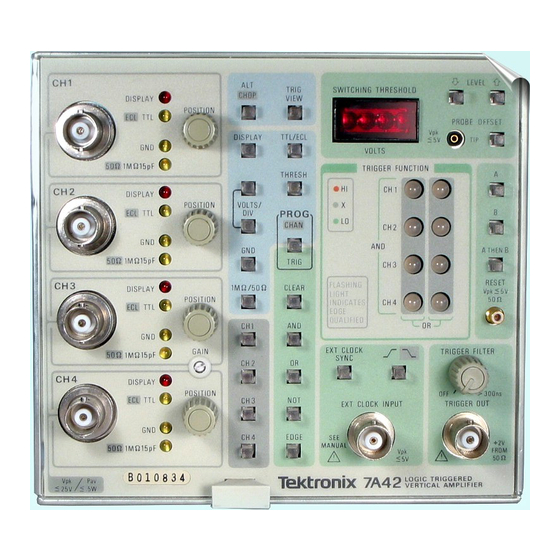
- Page 46 AND INDICATORS All controls, connectors, and indicators required for the normal operation of the 7A42 Logic Triggered Vertical Amplifer unit are located on the front panel. Figure 2-7 shows an exploded front panel and gives a brief functional description of each control, connector, and indicator.
- Page 48 ushbutton selects one of two modes; when PROG CHAN or RIG — light is on, those controls associated with programming the TRIGGER FUNCTION are operable (see 6, 7 and 10). When light is out, those controls associated with CH1, CH2, CH3, CH4 setup conditions are operable (see 6 and 2).
- Page 49 Operating Instructions — 7A42 ® The following controls, connectors, and indicators are common to CH1, CH2, CH3, and CH4. for signal connection. Input Connector — BNC Vertically positions the incoming signal. POSI ION — Clockwise rotation moves displayed trace upward.
- Page 50 Operating Instructions — 7A42 ® Variable control sets minimum duration of RIGGER FIL ER — TRIGGER FUNCTION output before it is sent to the time base or TRIGGER OUTput connector. RIGGER OU — rovides a front-panel output of the trigger signal.
- Page 51 GET-ACQUAINTED EXERCISES These Get-Acquainted Exercises will help you become familiar with the operation of your 7A42 and at the same time, check basic instrument operation. The Get- Acquainted Exercises are divided into three parts: Exercise 1 — reliminary Set Up and Initialization, Exercise 2 —...
- Page 52 INI IALIZA ION After completion of the 7A42 installation and power-up self-test sequence the next step is to initialize the 7A42 front-panel settings. To initialize the 7A42 front-panel controls to a known state, perform the following procedure: a. Set the ROG pushbutton 1 to the CHAN mode (pushbutton light out).
- Page 53 Operating Instructions — 7A42 d. Turn the oscilloscope mainframe ower off and then on again. e. After the self test is completed, the 7A42 front-panel status indicators and control lights should be as shown below. 4285-217 2-15...
- Page 54 NO E If continuin from Exercise 1, proceed with Exercise 2. If not, first perform Exercise 1 then proceed. Now that the 7A42 is properly installed and initialized, begin this exercise by performing the setup conditions as shown below: 2-16...
- Page 55 Operating Instructions — 7A42 As can be seen from the CH1 status indicators, CH1 has been previously initialized to TTL 1 and 1 MΩ 15 pf input 2. Observe that the TRIGGER FUNCTION has been set to trigger on a HI level of CH1 3.
- Page 56 Operating Instructions — 7A42 Now press the DIS LAY pushbutton 8, note that the CH1 DIS LAY indicator 9 extinguishes and that the channel 1 waveform 10 is no longer displayed on the crt. The trigger view trace 11 is now displayed at the bottom of the crt (TRIG VIEW pushbutton is illuminated 12).
- Page 57 Operating Instructions — 7A42 ress the GND pushbutton 17. Notice that the CH1 GND indicator 18 is illuminated and that the CH 1 waveform 19 and TRIG VIEW waveform 20 are replaced by a baseline trace (the CH1 input is now referenced to ground).
- Page 58 Operating Instructions — 7A42 ress the ROG pushbutton 25. The pushbutton light is now green which indicates that the ROG TRIG ( rogram Trigger) mode has been selected. ress the CLEAR pushbutton 26 and notice that the CH1 TRIGGER FUNCTION indicator 27 extinguishes, the CH1 display 28 free-runs (is not triggered), and the TRIG VIEW waveform 29 disappears.
- Page 59 Operating Instructions — 7A42 ress the CH1 pushbutton 30. The CH1 TRIGGER FUNCTION indicator 31 is now red (indicating an active HI trigger level). Both the CH1 waveform 32 and the TRIG VIEW waveform 33 are again triggered. ress the NOT pushbutton 34. Notice that the CH1 TRIGGER FUNCTION light 35 is now green, and that the CH1 display 36 is triggered on the LO level of the CH1 signal.
- Page 60 Operating Instructions — 7A42 ress the NOT pushbutton 37. Notice that the display is triggered on the CH1 HI level 38, and the CH1 TRIGGER FUNCTION indicator is red 39 (two presses of the NOT pushbutton cancel each other). Set the time-base Time/Division to 100 ns and rotate the oscilloscope Intensity control clockwise to view the trace.
- Page 61 Operating Instructions — 7A42 ress the NOT pushbutton 44, the display is now triggered on the falling edge of CH1 45 and the CH1 TRIGGER FUNCTION indicator 46 is now flashing green. ress the EDGE pushbutton 47, the display is now triggered on the LO level of CH1 48.
- Page 62 Operating Instructions — 7A42 ress the NOT pushbutton 50 to return the display triggering to the HI level of CH1 51. Set the time-base Time/Div control to 500 µs 52. ress the AND pushbutton 53, then press the CH2 pushbutton 54 and notice that the CH2 TRIGGER FUNCTION indicator 55 illuminates red (CH1 56 remains red).
- Page 63 Operating Instructions — 7A42 ress the CLEAR pushbutton 58 (the CH1 and CH2 TRIGGER FUNCTION indicators 59 extinguish). ress the CH1 pushbutton 60. The TRIGGER FUNCTION requirements are now met and the CH1 display is again triggered 61. 2-25...
- Page 64 ROG CHAN mode (pushbutton light out). Check the CH1 display for a 2 division square-wave signal 63. If necessary adjust the 7A42 GAIN 64 (front-panel screwdriver adjustment) for exactly 2 divisions of display (position display as necessary). Select CH2 for display by first pressing the CH2 pushbutton 65 and then pressing the DIS LAY pushbutton 66.
- Page 65 Operating Instructions — 7A42 Move the oscilloscope calibrator signal from the CH1 input connector 69 to the CH2 input connector 70. Notice that the square-wave display 71 is free-running (not triggered). Rotate the OSITION control 72 and notice that the square wave is displayed on CH2.
- Page 66 Operating Instructions — 7A42 To remove the CH1 trace from the crt display first press the CH1 pushbutton 76 and then press the DIS LAY pushbutton 77. Observe that the CH1 trace and deflection factor readout 78 are no longer displayed.
- Page 67 Operating Instructions — 7A42 ress the NOT pushbutton 85 and notice that the TRIGGER FUNCTION CH2 indicator 86 is green (green TRIGGER FUNCTION indicator denotes an active LO trigger level). Notice that the CH2 display 87 is triggered on the LO level of the calibrator signal.
- Page 68 Operating Instructions — 7A42 To set the vertical deflection factor of CH2, select the rogram Channel Mode by pressing the ROG pushbutton 91 so that the pushbutton light is extinguished, then press the CH2 pushbutton 92. ress the upper VOLTS/DIV pushbutton 93 once for a deflection factor of 0.2V as displayed on the crt readout 94.
- Page 69 Operating Instructions — 7A42 Move the oscilloscope calibrator signal from the CH2 input connector 100 to the CH3 input connector 101. Notice that the TRIG VIEW waveform 1 02 is no longer displayed. Select CH3 for display by first pressing the CH3 pushbutton 103 and then the DIS LAY pushbutton 104.
- Page 70 Operating Instructions — 7A42 To set TRIGGER FUNCTION requirements for CH3, select the rogram Trigger mode by pressing the ROG pushbutton 108 so that the pushbutton light is green. Remove the CH2 TRIGGER FUNCTION by pressing the CLEAR pushbutton 109. Now, press the CH3 pushbutton 110. Notice that the CH3 TRIGGER FUNCTION indicator 111 illuminates red.
- Page 71 Operating Instructions — 7A42 To display Channel 4, press the CH4 pushbutton 118 and then press the DIS LAY pushbutton 119. Move the oscilloscope calibrator signal from the CH3 input connector 1 20 to the CH4 input connector 121. Observe that the channel 4 display 122 is not triggered. The CH4 display is not triggered because no TRIGGER FUNCTION requirements have been selected for CH4 and therefore no signal is displayed on the TRIG VIEW trace 123 .
- Page 72 Operating Instructions — 7A42 To remove the CH3 trace 124 from the CRT display, first press the CH3 pushbutton 125 and then press the DIS LAY pushbutton 126. To set TRIGGER FUNCTION requirements for CH4 press the ROG pushbutton 127 ( rogram Trigger mode). Then remove the CH3 TRIGGER FUNCTION by pressing the CLEAR pushbutton 128.
- Page 73 Operating Instructions — 7A42 To change the CH4 vertical deflection factor 132 , press the ROG pushbutton 133 so that the light is extinguished. ress the CH4 pushbutton 134, and then press the upper VOLTS/DIV pushbutton 135 once for 0.2V as displayed on the crt readout 132.
- Page 74 LOGIC RIGGERING Exercise 3 demonstrates the use of the 7A42 TRIGGER FUNCTION feature, using two of the four input channels (CH1 and CH4). CH1 and CH4 were arbitrarily selected; we could have selected any two of the four input channels.
- Page 75 Operating Instructions — 7A42 erform the following setup: OSCILLOSCOPE OSCILLOSCO E OWER ......................ON VERTICAL MODE ..................LEFT HORIZONTAL MODE ..................B B TRIGGER SOURCE ..............LEFT VERT ULSE GENERATOR ERIOD ....................... 2 µS DELAY ......................0.1 µS VARIABLE DELAY ..................CAL DURATION ....................
- Page 76 Operating Instructions — 7A42 ress the 7A42 upper VOLTS/DIV pushbutton 1 twice for a 1V per division deflection factor, as shown on the Channel 1 CRT readout 2. Use the CH1 OSITION control 4 as necessary to move the square wave 3 (approximately 2.5 divisions in amplitude) so that it can be viewed on the ert,...
- Page 77 LO level near the ground reference 11. ress the THRESH pushbutton 12 (pushbutton light on). ress and hold the 7A42 ↑ LEVEL control 13 and notice that the SWITCHING THRESHOLD display 14 increases from the default setting of 1.4 V. Notice that when the SWITCHING THRESHOLD display reaches about 2.5 volts (the...
- Page 78 Operating Instructions — 7A42 ress the TTL/ECL pushbutton 17 twice and notice that the SWITCHING THRESHOLD display 18 defaults to 1.4 V. The CH1 deflection factor also defaults to 5 V/division 19 (the minimum display size available). ress the CH4 pushbutton 20, then press the DIS LAY pushbutton 21. Notice that the CH4 pushbutton 20 and the CH4 DIS LAY status lights 22 are now illuminated red.
- Page 79 Operating Instructions — 7A42 ress the GND pushbutton 24 and notice that the CH4 GND indicator 25 is illuminated and that a baseline trace is displayed for CH4. Use the CH4 OSITION control 26 to move the CH4 trace to the second horizontal graticule line up from reference.
- Page 80 CH4 signal is HI 42. ress the NOT pushbutton 43 and notice that the CH4 TRIGGER FUNCTION indicator 44 changes to green (active LO). Now the 7A42 will produce a trigger when CH1 is HI and CH4 is LO.
- Page 81 Set the time-base Holdoff control so that the display is double triggered. A stable trace can now be obtained by using the 7A42 TRIGGER FILTER control. Rotate the TRIGGER FILTER control 48 clockwise until the narrower of the two TRIGGER VIEW pulses 49 disappears 50.
- Page 82 Operating Instructions — 7A42 ress the NOT pushbutton 51 and notice that the CH4 TRIGGER FUNCTION indicator 52 is red (active HI). ress the EDGE pushbutton 53. Notice that the CH4 TRIGGER FUNCTION indicator 52 is flashing to indicate EDGE qualified triggering. Set the time-base Time/Div to 100 ns 54.
- Page 83 Operating Instructions — 7A42 ress the NOT pushbutton 60 and the EDGE pushbutton 61. Notice that the CH4 TRIGGER FUNCTION indicator has stopped flashing 62 (steady red) and that the TRIG VIEW display 63 is HI during the time that CH1 64 and CH4 65 are both HI.
- Page 84 Operating Instructions — 7A42 ress the B pushbutton 74 and then the CH4 pushbutton 73. Adjust the time base Holdoff control for a stable display. Vary the pulse generator Delay control and notice that a trigger is displayed on the TRIG VIEW trace 76 while the CH4 pulse 77 is HI, regardless of the CH1 signal 78 being HI or LO.
- Page 85 Operating Instructions — 7A42 ress the A THEN B pushbutton 80 and while varying the pulse generator Delay control, notice that a trigger occurs on the TRIG VIEW trace 81 only on the leading edge of the first CH4 pulse 82 following the falling edge of the CH1 trace 83.
- Page 86 Operating Instructions — 7A42 DETAILED O ERATING INFORMATION Detailed information concerning the controls and operation of the 7A42 is given in the following pages. SELF- ES NO E Disconnect any cables from the RESET, EXT CLOCK, and TIP inputs while Self Test is in pro ress (an external impedance on these connectors may cause a Self Test failure).
- Page 87 Self-test failures are indicated by three different methods: 1. on the mainframe crt, 2. on the 7A42 SWITCHING THRESHOLD display, and 3. on the TRIGGER FUNCTION indicators. Figure 2-11 illustrates a typical self-test failure, indicated by the three display methods.
- Page 88 The severity information is helpful in determining if the 7A42 can still be used for the intended purpose or whether repair is necessary. To continue the self-test sequence, press any of the 7A42 front-panel pushbuttons.
- Page 89 Operating Instructions — 7A42 ABLE 2-1 7A42 Belt- est Failure Messages RIGGER FUNC ION SWI CHING HRESHOLD Severity of failure; VOL S and crt readout display (LED display) functional usability of Instrument Indication Indication ossible loss CH1, 01 to 04...
- Page 90 FRON -PANEL INI IALIZA ION While getting acquainted with the 7A42, it might be desirable to begin operation with the front-panel controls set to a known state (initialized). The front panel will initialize to the control settings listed in Table 2-2 and as shown in Figure 2-12. To initialize the 7A42 front-panel control settings, see Exercise 1 in the Get- Acquainted Exercises of this section.
- Page 91 Operating Instructions — 7A42 ABLE 2-2 7A42 Front-Panel Control Settings When Initialized Control Setting Control rogram Channel (light off) ROG CHAN/TRIG rogrammable Channel CH1 only DIS LAY CH1 only VOLTS/DIV (CH1 through CH4) reset to 0.5 V/Div at bnc input...
- Page 92 The battery-backup feature can be defeated if so desired; refer qualified service personnel to the 7A42 Service Manual. If the battery-backup feature has been disabled, the 7A42 front-panel control settings will return, at power up, to the settings listed in Table 2-2, and as shown in Figure 2-12.
- Page 93 Operating Instructions — 7A42 ABLE 2-3 7A42 Operator Message Summary Code Mnemonic Description and Corrective Action OVERLOAD A channel input is overloaded. Remove the overvoltage and unground the channels to continue operation. OFFSET ACQ A key was pressed while robe Offset acquisition was in progress.
- Page 94 The limited TTL/ECL VOLTS/DIV ranges require that attenuation be used to obtain useful signal levels at the 7A42 channel inputs. Ten times probes are recommended on the channel inputs to attenuate TTL and ECL signals; otherwise 10X attenuators should be used.
- Page 95 6131 and 6230 probes are recommended for use with the 7A42. The Tektronix 6131 is a 10X passive probe with 10 megohm at 10.8 picofarads. A variety of probe tips (hooks, IC grabber and ground leads) are available with this probe.
- Page 96 Operating Instructions — 7A42 Figure 2-13. Channel readout display. Figure 2-14. Channel readout display with 10X probes attached to Inputs of CH1, CH2, CH3, and CH4. 2-58 REV JUL 1984...
- Page 97 (clockwise rotation moves the trace upward). GAIN This screwdriver control adjusts the 7A42 display output (of all four channels) to match the vertical gain tolerance of any Tektronix 7000-series mainframe. S A US INDICA ORS (CH1, CH2, CH3, CH4) Each channel has four status indicators (DIS LAY, ECL/TTL, GND and 50Ω/1MΩ).
- Page 98 A. The trigger output then takes place with the next occurrence of function B. After this cycle, the 7A42 will begin to look for another occurrence of function A, to begin the next nested trigger cycle.
- Page 99 TRIG VIEW trace refer qualified service personnel to the 7A42 Service Manual. If all of the channel displays are turned off the TRIG VIEW trace will be on and cannot be turned off.
- Page 100 ECL. To select the ECL mode refer qualified service personnel to the 7A42 Service Manual. The EXT CLOCK IN UT can be used with a 1X probe in TTL mode, or can be directly connected to the logic circuit in either TTL or ECL mode;...
- Page 101 Trigger Function B. A typical timing diagram depicting the Normal and A THEN B Gate modes, is shown in Figure 2-17. For selection of either mode refer qualified service personnel to the 7A42 Service Manual. The TRIGGER OUT signal levels are compatible with the RESET input levels.
- Page 102 Operating Instructions — 7A42 Figure 2-17. Example of A HEN B, level and EDGE sensitive RIGGER FUNC ION, showing the Normal and A HEN B Gate waveform alternatives. PROG CHAN/ RIG ROG CHAN/TRIG pushbutton selects one of two modes, ROG CHAN (program channel) or ROG TRIG (program trigger).
- Page 103 Operating Instructions — 7A42 CH1, CH2, CH3, CH4. In the ROG CHAN mode the CH1, CH2, CH3, and CH4 pushbuttons are used to select and indicate the channel which will respond to the TTL/ECL, VOLTS/DIV, GND, 1MΩ/50Ω, DIS LAY and THRESH pushbutton controls.
- Page 104 ROBE OFFSET button once again to acquire this offset measurement into the 7A42. The probe offset button will now light green and the probe tip may now be removed. The offset measurement remains in the display which is again indicating the SWITCHING THRESHOLD voltage.
- Page 105 EDGE pushbutton to select falling edge sensitivity. For example, the keystroke sequence CH1 EDGE programs the 7A42 to trigger on the rising transition of CH1; the keystroke sequence CH3 NOT EDGE sets it to trigger on the falling transition of CH3.
- Page 106 Operating Instructions — 7 A42 receive the ed e-sensitive status. The previous ed e-sensitive channel will become level-sensitive only. This is because only one ed e-sensitive channel per product is allowed. If the last entered channel is converted back to level-sensitive, the previous ed e-sensitive channel will a ain become ed e-sensitive.
- Page 107 SECTION THREE L ICATIONS Shown above is the Tektronix 7A42, 7B87, and 7D15 installed in a Tektronix 7854 Oscilloscope. The 7854 is a programmable waveform-processing oscilloscope that enables signal averaging, cursor measurements, and single-key waveform parameter measurements to save time and improve both accuracy and resolution.
- Page 108 7D15 225 MHz UNIVERSAL COUNTER/TIMER ..3-11 LICATION 6 — OFFSET ROBING TECHNIQUES FOR HIGH S EED LOGIC SYSTEMS ........3-14 LICATION 7 — USING THE 7A42 WITH THE 7854 ......3-17 LICATION 8 — USING THE 7A42 WITH THE 7104 ......3-18...
- Page 109 For example, the combinational triggering functions provided on the 7A42 front panel make it a simple matter to look at any count of a four-bit counter. A master clock signal can be connected to the 7A42 EXT CLOCK IN UT and displayed on the Trigger View trace.
- Page 110 Applications — 7A42 View trace is a representation of the trigger signal output, in the form of a small signal at the bottom of the CRT . This signal is sent to the time base and to the front ...
- Page 111 Applications — 7A42 enables the user to: 1) Qualify the Trigger Function on a positive or negative transition of the external clock input signal and 2) display that clock signal by selecting the Trigger View trace. Figure 3-2. Display of four channels with RIG VIEW trace.
- Page 112 The 7A42 features an automatic preset TTL or ECL threshold level. If a variable threshold is needed, enter the rogram Channel mode, turn the threshold monitor on, and select the channel whose threshold is to be varied. The LEVEL ↑...
- Page 113 Applications — 7A42 Figure 3-4. riggering on a low-amplitude puise. prevent triggering on these normal transitions, and at the same time allow the low amplitude pulse of a slightly longer duration to be detected.
- Page 114 Trigger Function features. In addition to recognizing logic high and low levels, the 7A42 can incorporate one edge sensitive channel into each product (AND function). Because each Trigger Function (A or B) can contain two products, two independent Edge operators per Trigger Function are available.
- Page 115 Read strobe. A positive transition on the 7A42's A THEN B Gate out will start the 7D1 1' s count. The 7D11 receives this gate signal internally through the 7000-series main interface. At the end of its programmed time interval, the 7D11 resets the 7A42.
- Page 116 Applications — 7A42 Figure 3-6. Set up to monitor invalid data transitions. Figure 3-7. he 7A42 captures a positive transition of data during the time data should be stable.
- Page 117 (CH3) except for an instant of time equal to driver A ’ s propagation delay. Set the 7A42 to trigger when the above condition is not met; that is, when the input and output do not match. At this time some other driver on the bus is overpowering driver A ’...
- Page 118 Applications — 7A42 Figure 3-8. Bus contention measurement set up. 3-10...
- Page 119 A THEN B Gate signal to gate the counting and timing system in the 7D15 allows a variety of difficult measurements. The 7D15 can measure the width of the 7A42 ’ s A THEN B Gate to determine how much time elapsed between Trigger Function A and Trigger Function B.
- Page 120 7D15 will count the number of clock cycles occurring between the two events. The 7A42's A THEN B Gate out is sent to the 7D15 via the 7000-series mainframe trigger path. This gate tells the 7D15 to count clocks on its “...
- Page 121 Applications — 7A42 7D15 Settings: Gate ....................Normal Mode ..................TIM Width A Averg ....................X10 Clock ....................10 ns Trigger A Source ................Trigger Source Slope ....................+ Coupling ................... DC Level ..................... reset Mainframe Settings: Set the Trigger Source for the compartment containing the 7D15 to Right Vertical.
- Page 122 50-ohm termination resistor that can be switched in for use with 1 megohm amplifiers. This 50-ohm termination will be switched out in this application in favor of the 7A42 ’ s internal 50 ohm terminator. A variety of grounding schemes are possible with the 6230, including a low-inductance ground lead, and a printed- circuit-board adaptor.
- Page 123 Applications — 7A42 PROBING ECL CIRCUI S ECL circuits are commonly operated with a -5.2 V and zero-volt Vee and Vcc supplies. For this configuration, a high logic level becomes -0.8V and a low logic level becomes -1.7V. The output of an ECL gate is the emitter of an N N transistor (emitter follower stage) whose collector is connected to ground.
- Page 124 When using the 6230, remember the first step is to acquire the probe offset value into the 7A42. Next set the Switching Threshold Voltage with the LEVEL buttons to a value appropriate for the logic family under test. The Switching Threshold Voltage at the probe tip is indicated in the numerical display.
- Page 125 You may notice the readout format change as channels are displayed or removed from the display. For example, .1 V may become 100 mV. This is normal for a 7A42 in the “ 7854 operational mode, ” and does not affect measurements.
- Page 126 The TEKTRONIX 7104 Oscilloscope is a one gigahertz mainframe that is an ideal companion to the 7A42 Logic Triggered Vertical Amplifier. The bandwidth of the 7104 accommodates the full specified 7A42 system bandwidth of 350 MHz for high speed logic.
- Page 127 SECTION FOUR INSTRUMENT O TIONS No options existed for the 7A42 at the time of this printing. Information about any subsequent options will be included in the CHANGE INFORMATION section at the back of this manual.
- Page 128 List of 3-0 2-56 ATTENUATING IN UT SIGNALS: (beep): 2-54 AUDIBLE MESSAGE B TRIGGER FUNCTION: 2-60 BATTERY BACKU : 2-52 Specification of: 1-21 BEE , AUDÏBLE OFF: 2-54 BLOCK DIAGRAM: Drawing: 2-1 Description of 7A42: BOOLEAN ALGEBRA: Discussion of: 2-3...
- Page 129 Index — 7A42 CABLES: 2-57 CHARACTERISTICS: See Specifications, 1-6 CH 1 , CH2, CH3, CH4: 2-10, 2-64, 2-67 CHO : 2-10, 2-60 CLEAR: 2-10, 2-67 CLOCK CYCLES BETWEEN EVENTS: 3-12 C O DES: Operator Error Summary: 2-50, 2-51, 2-52 COLOR USED IN THIS MANUAL: 1-1...
- Page 130 Index — 7A42 FALLING EDGE SENSITIVITY: 2-67 FIRMWARE VERSION NUMBER: 2-49 FRONT- ANEL CONTROLS: 2-10 Initialization of: 2-52 FUNCTION A: 2-12 FUNCTION B: 2-12 FUNCTION A THEN B: 2-12 FUNCTIONAL CIRCUIT BLOCKS: 2-1 G AIN : 2-11, 2-59 GET-ACQUAINTED EXERCISES: 2-13...
- Page 131 Index — M2 O ERATING TEM ERATURE: 1-3 O ERATOR MESSAGES: 2-54 O TIONAL ACCESSORIES: 1-24 O TIONS: Section 4 OR: 2-3, 2-10, 2-67 ACKAGING FOR SHI MENT: 1-5 HYSICAL, CHARACTERISTICS: 1-21 OSITION: 2-10? 2-59 RESET THRESHOLD: 2-65 ROBE OFFSET: 2-66, 3-16 ROBES: 1-3, 2-56, 2-57, 2-62 ROBE COM ENSATION: 2-57 ROBING ECL: 3-15...
- Page 132 Index — 7A42 S (cont) S ECIFICATION: 1-6 ELECTRICAL: 1-6 ENVIRONMENTAL: 1-21 HYSICAL: 1-22 STANDARD ACCESSORIES: 1-24 STATUS INDICATORS, CHANNEL: 2-59 SUM OF RODUCTS NOTATION: 2-5 SUM: 2-3 SWITCHING THRESHOLD VOLTS display: 2-65 THRESH: 2-10, 2-65, 2-66 TIME-BASE LUG-IN: 1-4 TIME BETWEEN EVENTS.
- Page 133 NO E The audible beep can be turned off; refer qualified Service Personnel to the 7A42 Service Manual (Volume 1 ). REV JUL 1984...
Need help?
Do you have a question about the 7A42 and is the answer not in the manual?
Questions and answers