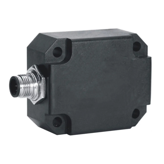
Summary of Contents for DIS Sensors CAN
- Page 1 CAN User Manual Inclination Safety Sensor (Type D) V2.0 CAN User Manual Inclination Safety Sensor (Type D)V2.0 Original instructions Page 1 of 18...
-
Page 2: Table Of Contents
CAN Object Dictionary Entries (Communication Profile section) ............11 CAN Object Dictionary Entries 360v device (Application Specific Profile section) ......13 CAN Object Dictionary Entries ±30h and ±90h devices (Application Specific Profile section) .... 15 EDS files ..............................17 Document revision control ........................17 Appendixes1 Schematic overview inclination measurement .............. -
Page 3: Introduction
• CAN communication profile: CAN Open (complies to CiA301 version 4.2.0 & EN50325-4) • CAN device profile: CiA410 DSP 2.0.0 for inclinometers • Baud-rate: default 125 kbit/s (can be set to 10, 20, 50, 125, 250, 500, 1000 kbit/s) • Node-ID: default 01h (possible range 01h – 7Fh, so max. 127 nodes) •... -
Page 4: Safety, Installation, Use & Maintenance
Actual value is specified in the datasheet • Configuration of the device like changing Node-ID, COB-ID’s and centring (sensor-offset) can only be done after a new CRC-code is generated separately and written to the device. -
Page 5: Certification
Example: a crane having a maximum tilt angle of the chassis. If the tilt angle of the chassis exceeds a certain critical value, the crane will fall over. To prevent for this an inclinometer can be mounted on the chassis, measuring the X- and Y tilt of the chassis. -
Page 6: Signal Processing
Default this output filter is disabled. Via the CAN object dictionary (index 300Eh) this filter can be controlled, by setting the time-constant in ms, with a maximum of the redundancy compare time (set by index 4006h sub-index 02h) . -
Page 7: Peak Suppression Filter
Filter principle: as inclination normally changes relative slow, a sudden peak in the inclination signal indicates an acceleration peak instead of a real inclination angle change. In this case, the filter can make the sensor ignore this peak for a certain time. -
Page 8: Accelerator Element Tolerance
±30°. For a ±90 device the angle is limited to ±90°. 8.8 Writing objects When writing an object it can have a major influence on the output. To prevent unauthorized changes most write action can only be executed when the device is in pre-operational state. According to EN 50325-5 8.9 Changing SRDO1 settings... -
Page 9: Internal Diagnostic Tests
(No SRDO, TPDO and Heartbeat). In this state, a NMT reset will not restart the sensor. Failure should be analyzed by reading out the emergency message. If the error can be fixed, give the sensor a new power cycle will restart the communication. If it is a ‘sensor element error (redundancy error), you might consider to update ‘redundancy compare time’... -
Page 10: Can Predefined Connection Object Id's
Sensor goes to safe state (stop state) when an error is reported. Sensor must be power cycled to restart. Example: Receive COB-id 81h with data 00h FFh 01h 80h 00h 00h 0Eh 08h 81 emergency message of node id 01h 00h FFh-> FF00h CAN Open device specific error code 01h-> error register object 1001h 80h 00h ->0080h... -
Page 11: Can Object Dictionary Entries (Communication Profile Section)
CAN User Manual Inclination Safety Sensor (Type D) V2.0 11 CAN Object Dictionary Entries (Communication Profile section) Table 4: Communication profile section Index Sub- Type Read/ Data Description Pre- index Write operational 1000h Device Type 3001019Ah = Inclination, C1 (360°) normal TPDO 3002019Ah = Inclination, C2 (±90°... - Page 12 = 0 ms (disable TPDO2) (Max. = 5000ms) To store communication specific parameters permanent into the EEPROM of the sensor CAN Object 1010h should be used, otherwise the changes will be lost after a power cycle. All not-specified indices and/or sub-indices are reserved for factory use only.
-
Page 13: Can Object Dictionary Entries 360V Device (Application Specific Profile Section)
CAN User Manual Inclination Safety Sensor (Type D) V2.0 12 CAN Object Dictionary Entries 360v device (Application Specific Profile section) Table 5 Application specific profile section for 360 degree device Index Type Read/ Data Description Pre- index Write operational 1381h... - Page 14 Number of entrees Pre-set value signature To store application specific parameters permanent into the EEPROM of the sensor CAN Object 1010h should be used, otherwise the changes will be lost after a power cycle. All not-specified indices and/or sub-indices are reserved for factory use only.
-
Page 15: Can Object Dictionary Entries ±30H And ±90H Devices (Application Specific Profile Section)
CAN User Manual Inclination Safety Sensor (Type D) V2.0 13 CAN Object Dictionary Entries ±30h and ±90h devices (Application Specific Profile section) Table 6: Application specific profile section for ±30h and ±90h devices Index Type Read/ Data Description Pre- index... - Page 16 Number of entrees Pre-set value signature To store application specific parameters permanent into the EEPROM of the sensor CAN Object 1010h should be used, otherwise, the changes will be lost after a power cycle. All not-specified indices and/or sub-indices are reserved for factory use only.
-
Page 17: Eds Files
The EDS-file does not contain a customer specific configuration description (the values of the object dictionary, like i.e. the chosen baud rate, TPDO1 event time, Node ID etc.). For this purpose the customer can generate a so called DCF-file (Device Configuration File) with all customer specific settings out of the EDS-file. The DCF file is in fact the incarnation of the EDS-file. -
Page 18: Appendixes1 Schematic Overview Inclination Measurement
CAN User Manual Inclination Safety Sensor (Type D)V2.0 Page 18 of 18 A. Appendixes1 Schematic overview inclination measurement X counts Longitudinal angle in degree X Y Z filtered Y counts Lateral angle in ∑ Z counts degree 100Hz 800Hz Longitudinal...


Need help?
Do you have a question about the CAN and is the answer not in the manual?
Questions and answers