Table of Contents
Advertisement
Advertisement
Table of Contents

Subscribe to Our Youtube Channel
Summary of Contents for Phoenix Contact TP 6000 HMI
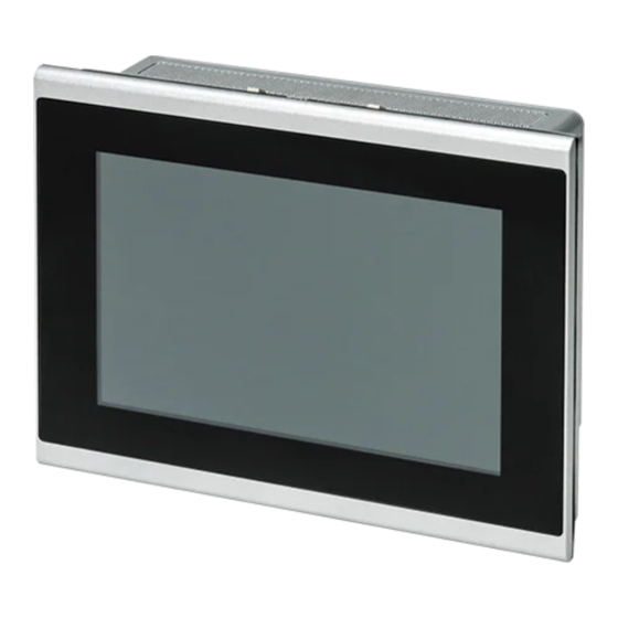
- Page 1 TP 6000 HMI for machine control User manual UM EN TP 6000...
- Page 2 This user manual is valid for: Designation Order No. TP 6070-WVPS 1189629 TP 6101-WXPS 1190417 TP 6121-WXPS 1190420 TP 6156-WHPS 1190421 TP 6185-WHPS 1190423 TP 6215-WHPS 1190424 PHOENIX CONTACT GmbH & Co. KG • Flachsmarktstraße 8 • 32825 Blomberg • Germany phoenixcontact.com...
-
Page 3: Table Of Contents
Serial communication ................13 Operation..........................15 Touchscreen ....................... 15 Power LED ......................15 Display......................... 15 Maintenance ..........................17 Fuse ........................17 Battery replacement .................... 17 Technical appendix........................19 Appendixes..........................23 List of figures ...................... 23 List of tables ....................... 25 1/28 PHOENIX CONTACT 4109_en_B... - Page 4 TP 6…PS 2/28 PHOENIX CONTACT 4109_en_B...
-
Page 5: For Your Safety
This device is intended for use in industrial environments. This device is state-of-the-art and has been built to the latest standard safety requirements. However, dangerous situations or damage to the machine itself or other property can arise from the use of this device. 3/28 PHOENIX CONTACT 4109_en_B... -
Page 6: Product Changes
(VPN) for remote maintenance access, firewalls, etc., for protection against unau- thorized network access. – On first request, you shall release Phoenix Contact and the companies associated with Phoenix Contact GmbH & Co. KG, Flachsmarkstrasse 8, 32825 Blomberg, Germany in accordance with §§ 15 ff AktG (German Stock Corporation Act), here- inafter collectively referred to as “Phoenix Contact”, from all third-party claims... -
Page 7: Overview And Ordering Data
Mounting clip for TP 6000 TP 6000 MOUNTING HW 1289537 CLIP (2PCS) Battery, real time clock TP 6000 RTC BATTERY KIT 1289761 MicroSDHC card, 16 GB, Industrial grade MICROSDHC-16GB 1154696 MicroSDHC card, 32 GB, Industrial grade MICROSDHC-32GB 1154699 5/28 PHOENIX CONTACT 4109_en_B... - Page 8 TP 6…PS 6/28 PHOENIX CONTACT 4109_en_B...
-
Page 9: Installation
Supporting panels must be at least 1.9 mm (14 gauge) to provide proper support. – Make sure there is adequate space around the heat sink on the unit and air inlets/out- lets to provide sufficient cooling. 7/28 PHOENIX CONTACT 4109_en_B... - Page 10 Overall and cutout dimensions with number of mounting clamps Display size Overall dimensions Cutout dimensions Number of mounting A (mm) B (mm) X (mm) Y (mm) clamps 7 in. 10 in. 12.1 in. 15.6 in. 18.5 in. 21.5 in. Cutout dimensions are ±0.5 mm 8/28 PHOENIX CONTACT 4109_en_B...
- Page 11 Loosen and remove the clamps securing the TP 6…PS in the panel. Using an assistant, press the retention clips along the top, and tilt the TP 6…PS for- ward. Lift the TP 6…PS so the bottom retention clips clear the panel, and remove. 9/28 PHOENIX CONTACT 4109_en_B...
-
Page 12: Vesa Mount
VESA mount The TP 6…PS includes a VESA MIS-D, 100, C hole pattern for attachment to an appropriate mount. Note that this standard is for devices up to 14 kg (30 lb.). Figure 3-3 VESA mount drawing 10/28 PHOENIX CONTACT 4109_en_B... -
Page 13: Interfaces
Connect a power source to the three-position removable connector. The connector (Order No. 1777992) accepts wire sizes from 0.5 to 2.5 mm² (24 to 12 AWG). Torque the wire-re- taining screws in the connector to 0.5 Nm (4.4 lb -in.). 11/28 PHOENIX CONTACT 4109_en_B... -
Page 14: Grounding
Lay the three conductors in the core and wrap them around the outside so a second strand is routed through the core. There must be between 3 and 5 cm of conductor be- tween the core and connector. Snap the core closed, taking care to not pinch the conductors. 12/28 PHOENIX CONTACT 4109_en_B... -
Page 15: Serial Communication
D-SUB 9 pinout D-SUB 9 pin Function RS-485 transmitted data plus RS-232 transmitted data RS-232 received data RS-485 received data plus Ground – Not used – Not used RS-485 transmitted data minus RS-485 received data minus 13/28 PHOENIX CONTACT 4109_en_B... - Page 16 TP 6…PS 14/28 PHOENIX CONTACT 4109_en_B...
-
Page 17: Operation
NOTE: Pixel failures, which can occur with TFT displays, are due to production and are not covered by the warranty. The operating device is equipped with different displays (see technical data) depending on variant. 15/28 PHOENIX CONTACT 4109_en_B... - Page 18 TP 6…PS 16/28 PHOENIX CONTACT 4109_en_B...
-
Page 19: Maintenance
Disconnect power from the TP 6…PS. Remove the unit from it’s mounting, either VESA or panel mount, and place it on a flat surface. Place the TP 6…PS on a towel to protect the display from damage. Figure 5-1 Battery replacement 17/28 PHOENIX CONTACT 4109_en_B... - Page 20 Secure the new battery in place using new double-stick tape (obtained locally). Plug the battery into the circuit board. Place the back cover on the unit and secure with the previously removed hardware. Torque screws to 0.5 Nm. Remount the TP 6…PS and apply power. 18/28 PHOENIX CONTACT 4109_en_B...
-
Page 21: A Technical Appendix
Removable screw-type and screw lug Conductor size 0.2 … 2.5 mm² (24 … 12 AWG) Torque, wire clamping screw 0.5 … 0.6 Nm RTC battery, typical life 5 years Fuse Integrated Protection against polarity reversal Diode 19/28 PHOENIX CONTACT 4109_en_B... - Page 22 Resolution, W x H (pixels) 800 x 480 Number of colors 16.7 million Touch technology PCAP (10 point) Brightness (cd/m²) Backlight Backlight MTBF (hours) 50000 Viewing angle (horizontal/vertical) 89° Panel cutout size, W x H (mm) 195 x 139 20/28 PHOENIX CONTACT 4109_en_B...
- Page 23 Resolution, W x H (pixels) 1920 x 1080 Number of colors 16.7 million Touch technology PCAP (10 point) Brightness (cd/m²) Backlight Backlight MTBF (hours) 50000 Viewing angle (horizontal/vertical) 85° Panel cutout size, W x H (mm) 388 x 263 21/28 PHOENIX CONTACT 4109_en_B...
- Page 24 Panel cutout size, W x H (mm) 522 x 336 Mechanical tests Impact load, shock test IEC 60068-2-27 Sinusoidal vibration IEC 60068-2-6 Conformance with EMC directives EN 61000-6-4, Class A EN 61000-6-2 Approvals CE compliant IEC 61131-2 22/28 PHOENIX CONTACT 4109_en_B...
-
Page 25: Appendixes
Panel mounting clamps ................. 9 Figure 3-3: VESA mount drawing ................10 Figure 3-4: Connectors and ports ................. 11 Figure 3-5: Power connection ................11 Figure 3-6: Ferrite core ..................12 Section 5 Figure 5-1: Battery replacement ................17 23/28 PHOENIX CONTACT 4109_en_B... - Page 26 TP 6…PS 24/28 PHOENIX CONTACT 4109_en_B...
-
Page 27: List Of Tables
List of tables List of tables Section 3 Table 3-1: Overall and cutout dimensions with number of mounting clamps ..8 Table 3-2: D-SUB 9 pinout..................13 Section 4 Table 4-1: Power LED meaning ................15 25/28 PHOENIX CONTACT 4109_en_B... - Page 28 TP 6…PS 26/28 PHOENIX CONTACT 4109_en_B...
- Page 29 The receipt of technical documentation (in particular user documentation) does not constitute any further duty on the part of Phoenix Contact to furnish information on modifications to products and/or technical documentation. You are responsible to verify the suitability and intended use of the products in your specific application, in particular with regard to observing the applicable standards and regulations.
- Page 30 Middletown, PA 17057 Should you have any suggestions or recommendations for improvement of the contents and layout of our manuals, please send your comments to: tecdoc@phoenixcontact.com 28/28 PHOENIX CONTACT GmbH & Co. KG • Flachsmarktstraße 8 • 32825 Blomberg • Germany phoenixcontact.com...
Need help?
Do you have a question about the TP 6000 HMI and is the answer not in the manual?
Questions and answers