Table of Contents
Advertisement
Quick Links
Unpacking and Installation, Rack SSPA
Revision ECO
1
Preliminary Release
2
Update to reflect new rear panel layout 06/16/2003 A.L. Crozier, Jr.
A
11267 Original Release
B
12115 Content Update
C
12372 Update to reflect CE compliance
D
13469 Add Power Connector Wiring Diagram 10/13/2005 L. dell'Aquila
MNC-0300-021
Record of Changes
Description
1 of 20
Unpacking and Installation, Rack SSPA
Date
Initiated By
03/10/2003 A.L. Crozier, Jr.
07/23/2003 A.L. Crozier, Jr.
04/21/2004 A.L. Crozier, Jr.
07/19/2004 A.L. Crozier, Jr.
Revision D
Advertisement
Table of Contents

Summary of Contents for Xicom SSPA
- Page 1 Unpacking and Installation, Rack SSPA Unpacking and Installation, Rack SSPA Record of Changes Revision ECO Description Date Initiated By 03/10/2003 A.L. Crozier, Jr. Preliminary Release Update to reflect new rear panel layout 06/16/2003 A.L. Crozier, Jr. 11267 Original Release 07/23/2003 A.L. Crozier, Jr.
-
Page 2: Table Of Contents
Unpacking and Installation, Rack SSPA........ - Page 3 Unpacking and Installation, Rack SSPA List of Figures Number Title Page Number Figure 1, Typical 4 Screw Mounting Flange Tightening Sequence ..... . . 8 Figure 2, Typical 8 Screw Mounting Flange Tightening Sequence .
- Page 4 Unpacking and Installation, Rack SSPA List of Tables Number Title Page Number Table 1, Waveguide Flanges ........... . . 11 Table 2, Waveguide Switches .
-
Page 5: Unpacking And Installation, Rack Sspa
Unpacking and Installation, Rack SSPA Unpacking and Installation, Rack SSPA Unpacking and Inspection Inspect the inside and outside of the shipping container for signs of damage. If any shipping damage is detected, call the shipping carrier and submit a damage report. -
Page 6: Waveguide Connection
Xicom recommends the use of Kapton® tape, 3M Brand, #92, Xicom P/N 602-0001-001. Remove tape or cap prior to final installation. - Page 7 Schutzkappe oder einem Band abgedeckt werden, das bei der Entfernung keine Kleberückstände hinterlässt. Xicom empfiehlt die Verwendung von Kapton® Band, Marke 3M, #92, Xicom P/N 602-0001- 001. Entfernen Sie das Band oder die Kappe vor der endgültigen Installation. Nichtbeachtung kann zur Verunreinigung des internen Hohlleitersystems oder des TWT führen und Schäden am Gerät zur Folge...
-
Page 8: Figure 1, Typical 4 Screw Mounting Flange Tightening Sequence
Unpacking and Installation, Rack SSPA Move to the screw diagonally opposite screw #3 and • partially tighten that screw (#4). If required, repeat this process for the remaining screws • (#5-#6, #7-#8). When you reach the first screw tightened in this step (#1) •... -
Page 9: Air Ducting Installation
The SSPA is cooled with a built-in fan. Heated exhaust air should not be recirculated into the SSPA. The air intake is located on the front of the SSPA, and an exhaust fan pulls air through the SSPA. A clearance of 6-8 inches from the exhaust is recommended to allow the heated exhaust air to clear the SSPA. -
Page 10: Rear Panel Interfaces
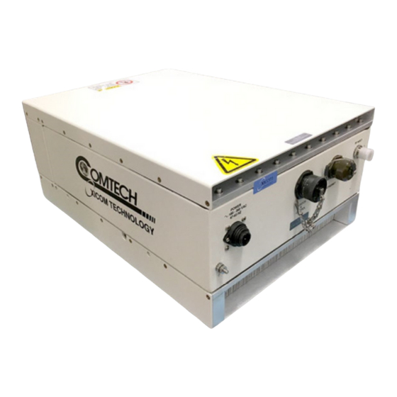
Unpacking and Installation, Rack SSPA Rear Panel Interfaces The rear panel (Figure 3) has all the connections required to use the SSPA. Not all of the connections are used in every configuration. The rear panel connections are: RF Output •... -
Page 11: Rf Output (J9) Waveguide Flange
Unpacking and Installation, Rack SSPA RF Output (J9) Waveguide Flange There are two waveguide flanges available. One for the C-Band SSPA and one for the Ku-Band SSPA. Table 1 lists the waveguide flanges. Table 1, Waveguide Flanges Frequency Band Flange Type... -
Page 12: Table 3, Waveguide Switch Connector (J3) Pinouts
WG SW1 Select B Ground WG SW2 Select A WG SW2 Select B Ground Ground Ground Summary Fault this SSPA Summary Fault other SSPA 21-23 Not Used SSPA A or (Not SSPA B) Select Ground MNC-0300-021 12 of 20 Revision D... -
Page 13: Auxiliary Interface Connector
Unpacking and Installation, Rack SSPA Auxiliary Interface Connector The Auxiliary Interface provides these interfaces for the use of the customer: Two sets of Form “C” Relay contacts for Summary Fault • Indication External Interlock Input • RF Inhibit Input •... - Page 14 Unpacking and Installation, Rack SSPA Pin Nr. Definition Comments +24 VDC Current limit of 100mA. +24 VDC Current limit of 100mA. 3 (Note Summary Fault 1 Normally Open. Closes when fault occurs. Summary Fault 1 Normally Closed. Opens when fault occurs.
-
Page 15: Summary Fault Indicators
Unpacking and Installation, Rack SSPA Summary Fault Indicators Two sets of Form C relay contacts (Summary Fault 1 and Summary Fault 2) are used to indicate that a fault has occurred. The Summary Fault 1 indicator signals change state any time an amplifier fault occurs. -
Page 16: Power And Interface Interconnections
Unpacking and Installation, Rack SSPA Power and Interface Interconnections When performing the procedures in this section refer to the Wiring and Interconnect Drawings for your specific amplifier. These drawings are located in the appendix titled Interconnect Drawings. Prime Power Connections The AC Prime Power receptacle (IEC-320 Connector) ) is located on the amplifier rear panel. -
Page 17: Com1 Rs-232 Interface (J5) (De-9 Pin)
Unpacking and Installation, Rack SSPA COM1 RS-232 Interface (J5) (DE-9 Pin) This port is used by the customer to connect to a remote RS-232 port. Table 4 lists the pinouts for COM1. COM 1 cannot be used for remote control when you are operating in the redundant mode. -
Page 18: Com2 Rs-485 Interface (J6) (De-9 Pin)
Unpacking and Installation, Rack SSPA COM2 RS-485 Interface (J6) (DE-9 Pin) This port is used by the customer to connect to a remote RS-485 port. This port may be either a 2-wire or 4-wire port. Table 5 lists the pinouts for COM2. Figure 6 and Figure 7 show the 2-wire and 4-wire implementation. -
Page 19: Ethernet (J7) (Eia T568B)
Unpacking and Installation, Rack SSPA Figure 7, Typical RS-485 4-Wire Full Duplex Implementation Ethernet (J7) (EIA T568B) The Ethernet Interface allows the user to connect the amplifier to a local network. Table 6 lists the Ethernet pinouts. Table 6, Ethernet Pinouts... -
Page 20: Grounding
Unpacking and Installation, Rack SSPA Grounding WARNING To prevent Electric Shock the amplifier should be securely connected to the grounding stud. Failure to comply could result in personnel injury or death. WARNUNG Zur Vermeidung elektrischer Schläge muss der Verstärker sicher mit der Erdklemme verbunden sein.
Need help?
Do you have a question about the SSPA and is the answer not in the manual?
Questions and answers