Table of Contents
Advertisement
Quick Links
INTRODUCTION
OPERATORS' MANUAL
Top Gun 206 MS
INVERTER Based Welding Machines
IMPORTANT: Read this Owner's Manual Completely before attempting to use this
equipment. Save this manual and keep it handy for quick reference. Pay particular
attention to the safety instructions we have provided for your protection. Contact your
distributor if you do not fully understand this manual.
Ⅰ I
Advertisement
Table of Contents
Troubleshooting

Summary of Contents for GENTRON 206 MS
- Page 1 INTRODUCTION OPERATORS’ MANUAL Top Gun 206 MS INVERTER Based Welding Machines IMPORTANT: Read this Owner’s Manual Completely before attempting to use this equipment. Save this manual and keep it handy for quick reference. Pay particular attention to the safety instructions we have provided for your protection. Contact your distributor if you do not fully understand this manual.
-
Page 2: Table Of Contents
CONTENT CONTENT §1 Safety..................... 1 §1.1 Symbols Explanation ....................1 §1.2 Machine Operating warnings! ..................1 §1.3 EMC device classification ................... 8 §1.4 EMC measure....................... 9 §1.5 Warning label ......................10 §2 Overview ..................11 §2.1 Brief Introduction ....................... 11 §2.2 Working Principle ...................... - Page 3 CONTENT §5 Maintenance & Troubleshooting ..........25 §5.1 Maintenance ....................... 25 §5.2 Troubleshooting ......................26 §5.3 List of error code ....................... 28 §5.4 Electrical schematic drawing ..................29 - II -...
-
Page 4: Safety
SAFETY §1 Safety Welding and cutting equipment can be dangerous to both the operator and people in or near the surrounding working area, if the equipment is not correctly operated. Equipment must only be used under the strict and comprehensive observance of all relevant safety regulations. - Page 5 SAFETY ELECTRIC SHOCK CAN KILL. Touching live electrical parts can cause fatal shocks or severe burns. The electrode and work circuit is electrically live whenever the output is on. The input power circuit and internal machine circuits are also live when power is on. In Mig/Mag welding, the wire, drive rollers, wire feed housing, and all metal parts touching the welding wire are electrically live.
- Page 6 SAFETY to two welders because voltage between the two can be the total of the open circuit voltage of both welders. When working above the floor level, use a safety belt to protect yourself from a fall should you get an electric shock! FUMES AND GASES CAN BE DANGEROUS.
- Page 7 SAFETY ARC RAYS: Harmful to people’s eyes and skin. Arc rays from the welding process produce intense visible and invisible ultraviolet and infrared rays that can burn eyes and skin. Use a shield with the proper filter and cover plates to protect your eyes from sparks and the rays of the arc when welding or observing open arc welding.
- Page 8 SAFETY WELDING SPARKS can cause fire or explosion. Welding on closed containers, such as tanks, drums, or pipes, can cause them to explode. Flying sparks from the welding arc, hot work piece, and hot equipment can cause fires and burns. Accidental contact of electrode to metal objects can cause sparks, explosion, overheating, or fire.
- Page 9 SAFETY chains, crane cables or other alternate circuits. This can create fire hazards or overheat lifting chains or cables until they fail. Rotating parts may be dangerous. Use only compressed gas cylinders containing the correct shielding gas for the process used and properly operating regulators designed for the gas and pressure used.
- Page 10 SAFETY Insure cylinders are held secure and upright to prevent tipping or falling over. Never allow the welding electrode or earth clamp to touch the gas cylinder, do not drape welding cables over the cylinder. Never weld on a pressurised gas cylinder, it will explode and kill you. Open the cylinder valve slowly and turn your face away from the cylinder outlet valve and gas regulator.
-
Page 11: Emc Device Classification
SAFETY Connect the work cable to the workpiece as close as possible to the area being welded. The people with heart-pacemaker should be away from the welding area. Noise can damage hearing. Noise from some processes or equipment can damage hearing. You must protect your ears from loud noise to prevent permanent loss of hearing. -
Page 12: Emc Measure
SAFETY hanker welding machines belong to Class A. §1.4 EMC measure In the special situation, The specified area may be affected, the standard of radiation limit value has been complied with (eg: The device, which is easy effected by electromagnetism, is used at the installation location, or there is radio or TV near the installation location). -
Page 13: Warning Label
SAFETY Shield the whole welding machine §1.5 Warning label The device with a warning label. Do not remove、 destroy or cover this label. These warnings are intended to avoid incorrect device operations that could result in serious personal injury or property damage. -10-... -
Page 14: Overview
OVERVIEW §2 Overview §2.1 Brief Introduction MIG SERIES arc welding machine adopts the latest pulse width modulation (PWM) technology and insulated gate bipolar transistor (IGBT) power module, which can change work frequency to medium frequency so as to replace the traditional hulking work frequency transformer with the cabinet medium frequency transformer. -
Page 15: Working Principle
OVERVIEW §2.2 Working Principle The working principle of MIG SERIES arc welding machine is shown as the following figure. Single-phase 220V work frequency AC is rectified into DC(350V) , then is converted to medium frequency AC (about 40KHz) by inverter device (IGBT), after reducing voltage by medium transformer (the main transformer) and rectifying by medium frequency rectifier (fast recovery diodes), and is outputted by inductance filtering. -
Page 16: Principles Of Welding
OVERVIEW §2.4 Principles of welding -13-... -
Page 17: Installation And Adjustment
OVERVIEW §3 Installation and Adjustment §3.1 Parameters Model MIG 206 MS Parameters Input Voltage (V) 1~240±10% Input Current (A) 38 MIG 46 MMA Input Power (KW) 5.1 MIG 4.7 MMA Welding Current (A) 40-200 MIG 10-200MMA No-load Voltage (V) 25% 200A 10% 200A Duty cycle(40℃)... -
Page 18: Equipment Connection
OVERVIEW figure. If the welding machine is overheating, the IGBT over-heat protection sensing will send a signal to the welding machine control unit to cut the output welding current OFF and light the over-heat pilot lamp on the front panel. In that case, the machine should not be welding for 10-15 minutes to cool down with the fanrunning. -
Page 19: Mig Welding- Gasless Wire
OVERVIEW §3.3.2 MIG Welding- Gasless wire §3.3.3 MMA Welding Connection of Output Cables Two sockets are available on this welding machine. For MMA welding the electrode holder is shown be connected to the positive socket, while the earth lead (work piece) is connected to the negative socket, this is known as DCEP. However various electrodes require a different polarity for optimum results and careful attention should be paid to the polarity, refer to the electrode manufacturers information for the correct polarity. -
Page 20: Maintenance Of Mig Gun Mechanism
OVERVIEW §3.4 Maintenance of MIG Gun mechanism §3.4.1 Dissection graphics for the MIG GUN IFT0063 螺丝 M4X6 UNI 6107 IHJ0645 二氧化碳欧式后把套 ICG6000 导电嘴扳手 IHJ0028 电缆护套 12-16-25 MMQ IIC0500 §3.4.2 Parts list for the MIG GUN 带绝缘层送丝管0.6-0.8 3米 蓝色 ICN0663 同轴电缆组/16mmq/3米 IZT0071 送丝管锁紧螺母... -
Page 21: The Operation For The Mig Gun
OVERVIEW §3.4.3 the operation for the MIG GUN 1. Service the wire feed mechanism at least every time the reel is changed. ·Check the wear of the feed roll groove and change the feed roll when necessary. ·Clean the welding gun wire guide with compressed air. 2. - Page 22 OVERVIEW Unfasten the wire end from the reel, but hold on it all the time. Straighten the wire end for approximately 20 cm and cut the wire in the straightened location. Open the pressure control level which then opens the feed gear. Thread the wire through the wire’s rear guide to the gun’s wire guide.
-
Page 23: Operation
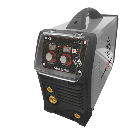
OVERVIEW §4 Operation §4.1 Machine Layout Description Front and rear panel layout of welding machine 1,MIG torch euro connector. 2,Positive (+) welding power output connection socket. 3,Spool gun connector. 4,Negative (-) welding power output connection socket. 5,Input power cable. 6,Power switch. 7,Gas inlet connector. - Page 24 OVERVIEW Control Panel of welding machine 1. Power indicator 2. Alarm indicator 3. VRD indicator 4. Spool Gun indicator 5. Function select 6. MIG model 7. MMA model 8. Gas check 9. Voltage indicator 10. Wave control indicator 11. Voltage adjust knob. 12.
-
Page 25: Welding Operation
THANK YOU FOR USING OUR PRODUCTS §4.2 Welding operation §4.2.1 MIG mode operation 1. Shielding Gas choice 1) When the wire material is Fe, the shielding gas is 80%Ar + 20%CO2 ; 2) When the wire material is Ss, the shielding gas is 98%Ar + 2%O2 ; 3) When the wire material is Al, the shielding gas is 100%Ar. - Page 26 THANK YOU FOR USING OUR PRODUCTS Material Root gap Wire Welding Welding Welding Gas-flow thickness G (MM) diameter current voltage speed rate (MM) (MM) (CM/MIN) (L/MIN) 60-70 16-16.5 50-60 75-85 17-17.5 50-60 10-15 80-90 17-18 50-60 10-15 Butt-joint 0-0.5 1.0/1.2 110-120 19-19.5 45-50...
-
Page 27: Operation Environment
THANK YOU FOR USING OUR PRODUCTS §4.4 Operation environment ▲ Height above sea level ≤1000 M ▲ Operation temperature range -10~+40°C ▲ Air relative humidity is below 90 %( 20°C) ▲ Preferable site the machine some angles above the floor level, the maximum angle does not exceed 15℃. -
Page 28: Maintenance & Troubleshooting
THANK YOU FOR USING OUR PRODUCTS §5 Maintenance & Troubleshooting §5.1 Maintenance In order to guarantee safe and proper operation of welding machines, they must be maintained regularly. Let customers understand the maintenance procedure of welding machines. Enable customers to carry on simple examination and inspections. Do your best to reduce the fault rate and repair times of welding machines to lengthen service life of arc welding machine. -
Page 29: Troubleshooting
THANK YOU FOR USING OUR PRODUCTS Using the dry compressed air to clear the inside of arc welding machine. Especially for clearing up the dusts on radiator, main voltage transformer, Monthly inductors, IGBT modules, fast recover diodes, PCB’s, etc. examinati Check the screws and bolts in the machine. - Page 30 THANK YOU FOR USING OUR PRODUCTS Troubles Reasons Solution Breaker damaged Change it Close the breaker, but Fuse damaged Change it the power light isn’t on Input power damaged Change it After welding machine Fan damaged Change it is over-heat, the fan The cable is loose Screw the cable tight doesn’t work...
-
Page 31: List Of Error Code
THANK YOU FOR USING OUR PRODUCTS §5.3 List of error code Error Type Error code Description Lamp status Yellow lamp(thermal Over-heating(1st thermal relay) protection) always on Yellow lamp(thermal Over-heating(2nd thermal relay) protection) always on Yellow lamp(thermal Thermal relay Over-heating(3rd thermal relay) protection) always on Yellow lamp(thermal Over-heating(4th thermal relay) -
Page 32: Electrical Schematic Drawing
THANK YOU FOR USING OUR PRODUCTS §5.4 Electrical schematic drawing -29-...
Need help?
Do you have a question about the 206 MS and is the answer not in the manual?
Questions and answers