Table of Contents
Advertisement
Advertisement
Table of Contents

Summary of Contents for Cooper Power Tools ARS-310/5
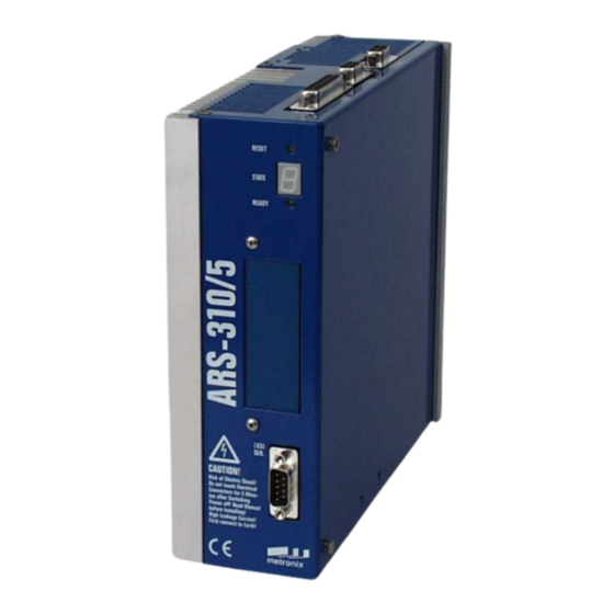
- Page 1 Product Manual Servo Positioning Controller ARS-310/5(UL) ARS-310/10 Metronix Meßgeräte und Elektronik GmbH Telefon: +49-(0)531-8668-0 Kocherstraße 3 Telefax: +49-(0)531-8668-555 D-38120 Braunschweig E-mail: vertrieb@metronix.de Germany http://www.metronix.de...
- Page 2 Any product names in this document may be registered trademarks. The sole purpose of any trademarks in this document is the identification of the corresponding products. Microsoft and Windows are either registered trademarks or trademarks of Microsoft Corporation in the United States and/or other countries. Product Manual “Servo Positioning Controller ARS-310/5(UL) ARS-310/10“ Version 2.3...
- Page 3 Description Revision index Date of change Release for distribution 09.12.2003 Numbers of AWG and 15.01.2004 marks about the (European standard) final corrections 03.02.2004 Correction of Windows® Trademark and CPT 2.3 10.01.2005 Product Manual “Servo Positioning Controller ARS-310/5(UL) ARS-310/10“ Version 2.3...
-
Page 4: Table Of Contents
RS232 interface .................26 3.4.2 CAN-Bus ..................26 3.4.3 Profibus..................26 3.4.4 I/O functions and device controller..........27 TECHNICAL DATA ..................28 Operating and display elements .............29 Supply [X9] .....................30 Motor connection [X6]................31 Motor feedback connection [X2] .............31 Product Manual “Servo Positioning Controller ARS-310/5(UL) ARS-310/10“ Version 2.3... - Page 5 Absolute positioning..............44 5.3.4 Driving profile generator.............44 5.3.5 Homing ..................45 MECHANICAL INSTALLATION...............46 Important notes..................46 View of the device ..................48 Mounting....................51 ELECTRICAL INSTALLATION ................53 Connector configuration................53 ARS-310/xx complete system..............54 Connection: Power supply [X9]...............56 Product Manual “Servo Positioning Controller ARS-310/5(UL) ARS-310/10“ Version 2.3...
- Page 6 Pin configuration [X21] (additional 15-pole connector)....71 7.9.4 Cable type and design [X21] additional 15-pole connector ..73 7.10 Connection: Incremental encoder input [X10].........75 7.10.1 Device side [X10] ...............75 7.10.2 Counterplug [X10] ..............75 Product Manual “Servo Positioning Controller ARS-310/5(UL) ARS-310/10“ Version 2.3...
- Page 7 Assembly Instructions for the EMC Kit:........88 8.5.3.1 Alternative in case of restricted room ............89 8.5.4 EMC Kit applications..............89 ESD protection ..................90 INITIAL OPERATION ..................91 General notes on connection..............91 Tools / material ..................91 Connecting the motor ................91 Product Manual “Servo Positioning Controller ARS-310/5(UL) ARS-310/10“ Version 2.3...
- Page 8 10.2.1 Display of operating mode and errors ........95 10.2.2 Error messages................95 INFORMATION CONCERNING UL..............99 11.1 Circuit protection..................99 11.2 Wiring and environment regards.............99 11.2.1 Motor and mains supply and sensor wiring according to AWG ..99 11.3 Overload behaviour ................99 Product Manual “Servo Positioning Controller ARS-310/5(UL) ARS-310/10“ Version 2.3...
- Page 9 Connection to power supply and motor ................53 Figure 11: Complete setup of the ARS-310/xx with motor and PC ..........55 Figure 12: Supply [X9] for the servo positioning controller ARS-310/5 (UL) .........57 Figure 13: Supply [X9] for the servo positioning controller ARS-310/10 ........57 Figure 14: Motor connection [X6]....................60...
- Page 10 Technical specifications: Incremental encoder input [X10] ..........39 Table 21: Technical specifications: Incremental encoder output [X11] ........39 Table 22: Pin configuration [X9]....................56 Table 23: ARS-310/5 (UL) Connector [X12]: External brake resistor...........58 Table 24: Pin configuration [X6]....................59 Table 25: Connector configuration: I/O communication [X1]............64 Table 26: Pin configuration [X2]....................66...
- Page 11 EMC requirements: First and second environment ............84 Table 36: content of the EMC kit ....................86 Tabelle 37: EMC-Components ......................89 Table 38: Display of operating mode and errors ................95 Table 39: Error messages ......................96 Product Manual “Servo Positioning Controller ARS-310/5(UL) ARS-310/10“ Version 2.3...
-
Page 12: General
Metronix Drive Control (MDC) Programming manual: This manual contains instructions for all steps necessary to design, produce and test applications based on MDC for the Servo Positioning Controller ARS-310/xx and IMD-F . Product Manual “Servo Positioning Controller ARS-310/5(UL) ARS-310/10“ Version 2.3... -
Page 13: Scope Of Supply
Content: 7-pole PHOENIX connector PC4/7-ST-7,62 Coding profile 9-pole DSUB connector, male 9-pole DSUB connector, female DSUB housing for 9-pole DSUB connector 25-pole DSUB connector, male DSUB housing for 25-pole DSUB connector Product Manual “Servo Positioning Controller ARS-310/5(UL) ARS-310/10“ Version 2.3... -
Page 14: Safety Notes For Electrical Drives And Controllers
Sound and safe operation of the servo drive controller requires proper and professional transportation, storage, assembly and installation as well as proper operation and maintenance. Only trained and qualified personnel may handle electrical devices: Product Manual “Servo Positioning Controller ARS-310/5(UL) ARS-310/10“ Version 2.3... - Page 15 Inappropriate handling of the servo drive controller and non-compliance of the warnings as well as inappropriate intervention in the safety features may result in property damage, personal injuries, electric shock or in extreme cases even death. Product Manual “Servo Positioning Controller ARS-310/5(UL) ARS-310/10“ Version 2.3...
-
Page 16: Danger Resulting From Misuse
The servo drive controller may be protected using an AC/DC sensitive 300mA fault current protection switch (RCD = Residual Current protective Device). Gold contacts or contacts with a high contact pressure should be used to switch the control contacts. Product Manual “Servo Positioning Controller ARS-310/5(UL) ARS-310/10“ Version 2.3... - Page 17 (European standard) VDE 0100 Regulations for the installation of high voltage (up to 1000 V) devices EN 60204 Electrical equipment of machines EN 50178 Electronic equipment for use in power installations Product Manual “Servo Positioning Controller ARS-310/5(UL) ARS-310/10“ Version 2.3...
-
Page 18: Safety Notes For Assembly And Maintenance
Carry out work in the machine area only, if AC and/or DC supplies are switched off. Switched off output stages or controller enablings are no suitable means of locking. In the case of a malfunction the drive may accidentally be put into action. Product Manual “Servo Positioning Controller ARS-310/5(UL) ARS-310/10“ Version 2.3... -
Page 19: Protection Against Contact With Electrical Parts
Otherwise the housing may carry high voltages which can cause electrical shock. Product Manual “Servo Positioning Controller ARS-310/5(UL) ARS-310/10“ Version 2.3... -
Page 20: Protection Against Electrical Shock By Means Of Protective Extra- Low Voltage (Pelv)
0 to 50 Volts. Only connect voltages and circuits with protection against dangerous voltages. Such protection may be achieved by means of isolation transformers, safe optocouplers or battery operation. Product Manual “Servo Positioning Controller ARS-310/5(UL) ARS-310/10“ Version 2.3...
Need help?
Do you have a question about the ARS-310/5 and is the answer not in the manual?
Questions and answers