Table of Contents
Advertisement
Quick Links
WARNING: READ BEFORE CONTINUING
To reduce the risk of fire, electric shock or injury to persons using this freezer, read all
instructions and follow basic safety precautions before using the unit, including the following:
Do not modify the plug provided with the freezer. If it will not fit the outlet,
have a proper outlet installed by a qualified electrician.
Do not position equipment so it is difficult to disconnect from the power supply.
freezer must be at least 6" away from any wall or object on any side.
While under warranty, do not attempt to repair or replace any part of the
freezer for servicing without first contacting the So-Low Service Department.
SAVE THESE INSTRUCTIONS
SALES OFFICE: 1001 Witmer Rd.,
Suite 700, Horsham, PA 19044
PHONE: (800)521-0754 FAX: (215)442-9202
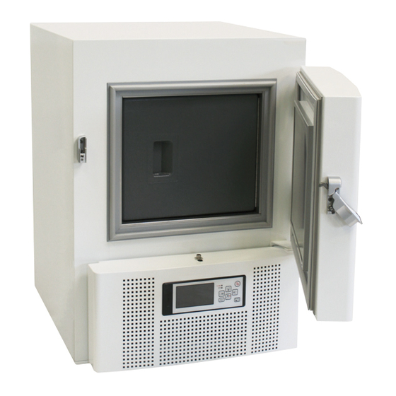
ULTRA LOW FREEZER
MV85 SERIES
INSTRUCTIONS
USER MANUAL
For parts replacement:
Email: parts@so-low.com
For technical support:
Email: service@so-low.com
CONTENTS
Advertisement
Table of Contents

Related Manuals for LabRepCo MV85 Series


Summary of Contents for LabRepCo MV85 Series
- Page 1 ULTRA LOW FREEZER MV85 SERIES INSTRUCTIONS USER MANUAL WARNING: READ BEFORE CONTINUING To reduce the risk of fire, electric shock or injury to persons using this freezer, read all instructions and follow basic safety precautions before using the unit, including the following: Do not modify the plug provided with the freezer.
- Page 2 ♦ SYMBOLS AND STARTING INSTRUCTIONS……………………….. ● MEANING OF ILLUSTRATED SYMBOLS…………………………………... ● STARTING INSTRUCTIONS………………………………………………….. ♦ UNIT REQUIREMENTS…………………………………………………. ● PRE-INSTALLATION INFORMATION………………………………………... ♦ GENERAL SPECIFICATIONS………………………………………….. ● TEMPERATURE SPECIFICATIONS…………………………………………. ● ELECTRICAL SPECIFICATIONS…………………………………………….. ♦ REFRIGERATION SPECIFICATIONS…………………………………. ♦ MAINTENANCE…………………………………………………………... ♦ UNIT OPERATION……………………………………………………….. ♦ TEMPERATURE CONTROL……………………………………………. ♦ ALARM OPERATION……………………………………………………. ●...
- Page 3 MEANING OF ILLUSTRATED SYMBOLS ILLUSTRATED SYMBOLS Various symbols are used in this safety manual in order to use the unit without danger of injury and damage of the unit. A list of problems caused by ignoring the warnings and improper handling is divided as shown below. Be sure that you understand the warnings and cautions in this manual before operating the unit.
-
Page 4: Pre-Installation Information
PRE-INSTALLATION INFORMATION RANGE OF ENVIRONMENTAL CONDITIONS FOR WHICH THIS EQUIPMENT IS DESIGNED Indoor use. Altitude up to 2000m. Ambient temperatures 15°C to 30°C ( 60°F TO 85°F ) Recommended humidity range of 30% to 90%. Mains supply fluctuations up to -5% to +10% of the nominal voltage. Transient over-voltages typically present on the mains supply (overvoltage category II). -
Page 5: Temperature Specifications
TEMPERATURE SPECIFICATIONS OPERATIONAL TEMPERATURE RANGE -40°C TO -85°C ELECTRICAL SPECIFICATIONS ELECTRICAL PLUG • Plug the freezer into the proper outlet with an adequate power supply. This unit requires a Dedicated Electrical Line. • MODEL VOLTAGE AMPERAGE PLUG 115 VOLTS MV85-1 15 AMP MV85-2 60 HERTZ... -
Page 6: Preventative Maintenance
MODEL REFRIGERATION SYSTEM REFRIGERANT MV85-1 0.25 3/8 HP REFRIGERATION SYSTEM EP88 – 6.10 OZ. MV85-2 3/8 HP REFRIGERATION SYSTEM EP88 – 6.88 OZ. MV85-3 3/8 HP REFRIGERATION SYSTEM EP88 – 6.90 OZ. MAINTENANCE PREVENTATIVE MAINTENANCE BEFORE PERFORMING MAINTENANCE... -
Page 7: Unit Operation
To reduce the risk of fire, electric shock or injury to persons using this freezer, read all instructions and follow basic safety precautions. CAUTION DISCONNECT THIS UNIT FROM THE POWER SUPPLY BEFORE PERFORMING MAINTENANCE ON THE UNIT. CLEANING PROCEDURE • Wipe down the exterior of the freezer with a soft cloth and spray type polish. -
Page 8: Temperature Control
It will now take about 6-10 hours before the set temperature is reached. The freezer should be cooled down empty. • WARNING WHEN FILLING THE UNIT WITH RACKS/BOXES, MAKE SURE TO PRE-COOL THEM IN ORDER NOT TO EFFECT THE INSIDE TEMPERATURE OF THE UNIT. WARNING THE INNER DOORS SHOULD BE USED AT ALL TIMES. -
Page 9: Alarm System
ALARM OPERATION ALARM SYSTEM... -
Page 10: Custom Settings
CONTROL PROGRAMMING CUSTOM SETTINGS... - Page 11 CONTROL PROGRAMMING ADVANCED SETTINGS...
-
Page 12: Service Settings
CONTROL PROGRAMMING SERVICE SETTINGS... -
Page 13: Advanced Service Settings
ADVANCED SERVICE SETTINGS DATA DOWNLOAD DOWNLOAD... -
Page 14: Factory Settings
UPLOAD FACTORY SETTINGS BASIC SETTINGS... -
Page 15: Advanced Settings
DEFAULT CUSTOMER DESCRIPTION SETTINGS SETTING PASSWORD 0000 TEMPERATURE SETPOINT -80.0 ALARM – DELAY 15 Min ALARM – DOOR OPEN Enable ALARM – HIGH TEMPERATURE ALARM – LOW TEMPERATURE ALARM – LOG TIME INTERVAL PROBE (EPROM) FAILURE Enable POWER FAILURE Enable ADVANCED SETTINGS DEFAULT CUSTOMER... - Page 17 MV85-1 DIAGRAM...
- Page 18 MV85-1 PARTS LIST...
- Page 19 MV85-2 DIAGRAM...
- Page 20 MV85-2 PARTS LIST...
- Page 21 MV85-3 DIAGRAM...
- Page 22 MV85-3 PARTS LIST...
Need help?
Do you have a question about the MV85 Series and is the answer not in the manual?
Questions and answers