Advertisement
1. OVERVIEW............................................................................................................................. 1
1.1. SPECIFICATIONS ........................................................................................................................ 2
1.1.1. Electrical...........................................................................................................................2
1.1.2. Physical............................................................................................................................2
1.2. COOLING ..................................................................................................................................... 2
1.2.1. Fan Exhaust ..................................................................................................................... 3
1.3. MOUNTING .................................................................................................................................. 3
1.4. POWER ........................................................................................................................................ 3
1.4.1. Turning the Power On and Off ......................................................................................... 3
1.4.2. Power Supply Status Indicators ....................................................................................... 4
2. FRAME STATUS FAULT CONDITIONS ................................................................................ 5
2.1. FRAME STATUS TALLY TERMINAL BLOCK ............................................................................ 5
3. INSTALLING AND REMOVING THE MODULES .................................................................. 5
3.1. OPENING AND CLOSING THE FRONT PANEL......................................................................... 5
3.2. INSTALLING THE MODULES ..................................................................................................... 6
3.3. REMOVING THE MODULES ....................................................................................................... 6
4. SERVICING INSTRUCTIONS................................................................................................. 6
4.1. CHANGING THE FUSES ............................................................................................................. 6
4.2. REPLACING THE POWER SUPPLY........................................................................................... 6
Figures
Figure 1: 500PS Status Indicators ......................................................................................................... 4
Figure 2: Locating the Power Supply Mounting Screw .......................................................................... 7
Tables
Table 1: Frame Status Tally Terminal Block Pin Assignments .............................................................. 5
Revision 1.4
Frame Manual
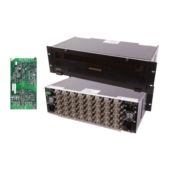
500FR 3 Rack Unit Frame
Advertisement
Table of Contents

Subscribe to Our Youtube Channel
Summary of Contents for evertz exponent 500FR
- Page 1 Frame Manual 500FR 3 Rack Unit Frame 1. OVERVIEW..........................1 1.1. SPECIFICATIONS ........................2 1.1.1. Electrical...........................2 1.1.2. Physical..........................2 1.2. COOLING ............................. 2 1.2.1. Fan Exhaust ........................3 1.3. MOUNTING ..........................3 1.4. POWER ............................3 1.4.1. Turning the Power On and Off ..................3 1.4.2.
-
Page 2: Revision History
Jul 06 Information contained in this manual is believed to be accurate and reliable. However, Evertz assumes no responsibility for the use thereof or for the rights of third parties, which may be effected in any way by the use thereof. Any representations in this document concerning performance of Evertz products are for informational use only and are not warranties of future performance, either express or implied. - Page 3 Frame Manual 500FR 3 Rack Unit Frame OVERVIEW The 500FR is a 3 rack unit high rack frame for the 500 series modular system. This advanced rack frame design can house up to 16 of the 500 series distribution, conversion and processing modules in any combination.
-
Page 4: Specifications
Frame Manual 500FR 3 Rack Unit Frame 1.1. SPECIFICATIONS 1.1.1. Electrical AC Mains Input Auto ranging, 100 240 VAC, 50/60 Hz Maximum Operating Current: 2.6 A (@ 120 VAC), 1.4 A (@ 240 VAC) Maximum Power Consumption: 200 W Maximum Module Load: 160 W (10 W per slot) Power Supply Configuration Dual, redundant, separate AC inlets... - Page 5 Frame Manual 500FR 3 Rack Unit Frame 1.2.1. Fan Exhaust The cooling fans for the power supplies, located at the front of the frame, draw air in the front and exhaust out the sides of the frame. The cooling fans for the modules, located at the rear of the frame, and draw air in the front and the exhaust out the rear of the frame.
- Page 6 ® If there is a fuse failure, contact Evertz customer service regarding the power supply immediately. The power supplies are short circuit protected and should not blow the fuse under a short circuit condition.
-
Page 7: Installing And Removing The Modules
Frame Manual 500FR 3 Rack Unit Frame FRAME STATUS FAULT CONDITIONS The Frame is fitted with a global Frame Status monitoring buss that is connected to each of the power supplies and to each of the modules. When a fault condition occurs on one of the power supplies, or one of the modules, a Frame Status Fault condition is active on the frame status buss. -
Page 8: Servicing Instructions
Frame Manual 500FR 3 Rack Unit Frame 3.2. INSTALLING THE MODULES Orient the module vertically such that the white card ejector is on the bottom. Align the card with the card guide corresponding to the slot number where you installed the rear panel plate. Carefully slide the module into the frame and press it completely into the rear panel connectors. - Page 9 Frame Manual 500FR 3 Rack Unit Frame The 500FR power supplies are hot swappable and can be easily replaced from the front without interrupting the signal integrity of the frame. Each power supply is capable of supplying full power to the frame by itself.
- Page 10 Frame Manual 500FR 3 Rack Unit Frame To replace the power supply the following procedure should be used. 1. Turn off the power supply switch 2. From the rear of the frame locate the power supply mounting screw. This screw is the top right screw holding the fan guard in place, and is indicated by the legend ↓...
Need help?
Do you have a question about the exponent 500FR and is the answer not in the manual?
Questions and answers