Table of Contents
Advertisement
Quick Links
5580 Enterprise Pkwy.
Fort Myers, FL 33905
Office: 239-694-0089
Fax: 239-694-0031
www.mcscontrols.com
MCS-MAGNUM
MCS Total
Solution
for all your
Control
Needs
BMS COMMUNICATION
MCS-BMS-GATEWAY
For Interfacing MCS-MAGNUM to:
Building Automation Systems Protocols:
MCS, Modbus RTU, Modbus IP, Ethernet,
BACnet IP, BACnet MS/TP, N2, *LonWorks
Manual supports the following:
MCS-BMS-GATEWAY - see Chapter 4 & 5 for installation
MCS-BMS-GATEWAY-NL-see Chapter 4 & 5 for installation
MCS-BMS-GATEWAY-N54-see Chapter 6 for installation
MCS-BMS-Gateway Models
• MCS-BMS-GATEWAY
with LonWorks
• MCS-BMS-GATEWAY-NL
(NO LonWorks)
• MCS-BMS-GATEWAY-N54
(NO LonWorks)
Ethernet
Energy Efficient and
RoHS Compliant
Rev. 3.5 May 24, 2022
RS485
OR
RS485
Internet
Router
MCS-Touch
Building
Management
System
Advertisement
Table of Contents

Summary of Contents for Micro control systems MCS-BMS-GATEWAY-see
- Page 1 Rev. 3.5 May 24, 2022 BMS COMMUNICATION MCS-BMS-GATEWAY For Interfacing MCS-MAGNUM to: 5580 Enterprise Pkwy. Fort Myers, FL 33905 Building Automation Systems Protocols: MCS, Modbus RTU, Modbus IP, Ethernet, Office: 239-694-0089 Fax: 239-694-0031 BACnet IP, BACnet MS/TP, N2, *LonWorks www.mcscontrols.com Manual supports the following: MCS-BMS-GATEWAY - see Chapter 4 &...
- Page 2 PH:(239) 694-0089 FAX:(239) 694-0031 www.mcscontrols.com All information contained within this document is considered to be proprietary information of Micro Control Systems, Inc. No information or data from this document shall be published, used, reproduced, transmitted, or disclosed to others outside your organization without the prior expressed written consent of Micro Control Systems, Inc.
-
Page 3: Table Of Contents
Table of Contents Chapter - 1. MCS-BMS-GATEWAYS .......................5 1.1. MCS-BMS-GATEWAY (Model with LonTalk) ....................5 1.1.1 LONTALK Protocol ..........................5 1.2. MCS-BMS-GATEWAY-NL (Model NO LonTalk) ...................5 1.3. MCS-BMS-GATEWAY-N54 (Model NO LonTalk) ..................5 Chapter - 2. NETWORK PROTOCOLS ....................6 2.1. MCS-MAGNUM BMS PROTOCOLS ......................6 2.1.1 BACnet OVER IP PROTOCOL ......................6 2.1.2... - Page 4 8.9. MCS Compressor Control State Chart .......................67 Chapter - 9. ALARMS- UNIT/COMPRESSOR / MODBUS ............68 9.1. Unit Alarms ..............................68 9.2. Compressor Alarms ............................69 9.3. MODBUS Alarms ............................71 Chapter - 10. CREATING CSV FILES USING MCS-CONFIG ............76 9.4. How to Create CSV Files: ...........................76...
-
Page 5: Chapter - 1. Mcs-Bms-Gateways
Chapter - 1. MCS-BMS-GATEWAYS The MCS-BMS-GATEWAY is a microprocessor based communication device that provides protocol translation from difference protocols. Information that can be transmitted includes the status of control points, alarm information, digital inputs, analog inputs or setpoints. The MCS-BMS-GATEWAY protocol is field selectable by setting jumper on the device. Using MCS-CONFIG and the CONFIG file for the MCS-MAGNUM, you can automatically create the program that is re- quired by the MCS-BMS-GATEWAY. -
Page 6: Chapter - 2. Network Protocols
Chapter - 2. NETWORK PROTOCOLS 2.1. MCS-MAGNUM BMS PROTOCOLS The following Protocols are available with the Magnum. Changes can be made to the settings using the Keypad or can be made using MCS-CONNECT SERVICE WINDOW. 1. BACnet IP 2. MCS PROTOCOL 3. -
Page 7: Modbus Rtu Protocol
2.1.3 MODBUS RTU PROTOCOL The Modbus RTU address can be verified and changed (with the proper authorization code) from the keypad/LCD or can be made using MCS-CONNECT SERVICE WINDOW.. The following steps will display the Modbus RTU Network address, and the Baud Rate: Press the Menu key, select Serv Tools, and then press the Enter key. -
Page 8: Protocols Mcs Controllers Support
2.3. Protocols MCS controllers support: 1. BACnet 2. MODBUS RTU 3. ETHERNET 4. MCS 5. JOHNSON N2 = Built in Support MCS Network Protocol Support Magnum MicroMag BACnet MCS BACnet RouterR2 Over Ethernet Modbus IP In Development ... -
Page 9: Mcs-Magnum Using Rs-485
2.4. MCS-MAGNUM USING RS-485 Using the RS485, the MCS-Magnum can be connected to the BMS (Modbus RTU or MCS 485) MCS-MAGNUM Building Management MCS-MAGNUM System RS485 MCS-MAGNUM... -
Page 10: Wiring Multiple Mcs Controllers
2.5. Wiring Multiple MCS Controllers Using the RS485, the network must be wired controller to controller „ Star configurations not allowed „ Up to 30 controllers can be wired togetherMCS-MAGNUM USING ETHERNET „ 04-14-2022... -
Page 11: Example Network
Using the Ethernet, the MCS-Magnum can be connected to: „ BMS (BACnet IP or Modbus IP) „ MCS-Touch (MCS-Connect) „ PC (MCS-Connect) „ Internet access through router (which allows connection via MCS-Connect from anywhere) „ Ethernet 2.6. EXAMPLE NETWORK 2.6.1 Standalone MCS-Magnum MCS-Touch „... -
Page 12: Multiple Mcs-Magnum Enclosures
2.6.2 MULTIPLE MCS-MAGNUM ENCLOSURES Internet Access „ BMS (BACnet IP or Modbus IP) „... -
Page 13: Multiple Mcs-Magnum Bms Rs485 Wiring Diagram
2.7. MULTIPLE MCS-MAGNUM BMS RS485 WIRING DIAGRAM 04-14-2022... -
Page 14: Chapter - 3. Mcs-Bms-Gateway & Nl Fieldserver Toolbox
Chapter - 3. MCS-BMS-GATEWAY & NL FIELDSERVER TOOLBOX Revision: 2.A The latest update to the user interface utility called FieldServer Toolbox has been introduced. This updated utility is available on the web for all FieldServer Gateways and enables users to easily: Search the local network for any connected FieldServers. - Page 15 Home Allows the user to check the status of the FieldServer gateway, including the configuration code, version, memory, gateway type and more. Under “Settings” the user has access to important network information. NOTE: The “System Restart” button at the bottom of the page is used to restart the FieldServer gateway (only on the Home page).
- Page 16 Select “Map Descriptors” to view the Map Descriptors setup in the gateway and clicking on the specific map descriptor will access the Map Descriptors detail page. Again, tabs across the top of the page provide quick access to settings, status, info stats, and error stats. User Messages Allows access to error messages, info messages and driver messages.
-
Page 17: Chapter - 4. Setup-Mcs-Bms-Gateway & Gateway-Nl
*Customer ProtoCarrier Startup Guide LONWORKS (FPC-C35): COMMISSIONING PROTOCARRIER ON A Chapter - 4. Setup-MCS-BMS-GATEWAY & GATEWAY-NL LONWORKS NETWORK Commissioning may only be performed by the LonWorks administrator. 4.1. Record Identification Data Each MCS-BMS-GATEWAY has a unique part number located on the side or the back of the unit. This number should Commissioning ProtoCarrier FPC-C35 on a LonWorks Network be recorded, as it may be required for technical support. -
Page 18: Bms Network Settings
*Customer ProtoCarrier Startup Guide • For Windows XP and Windows 7, select: Use the following IP Address For Windows XP and Windows 7, select: Use the following IP Address 192 . 168 . 18 . 201 255 . 255 . 255 . 0 192 . -
Page 19: Bacnet Ms/Tp And Bacnet/Ip: Setting The Device Instance
NOTE: Never set a BACnet MS/TP MAC Address from 128 to 255. Addresses from 128 to 255 are Slave Addresses and can not be discovered by BMS Front Ends that support auto discovery of BACnet MS/TP devices. Set DIP switches A0 – A7 to assign MAC Address for BACnet MS/TP for the MCS-BMS-GATEWAY FPC-ED4. Please refer to Appendix A.1 for the complete range of MAC Addresses and DIP switch settings. -
Page 20: Baud Rate Dip Switch Selection
4.3.5.1. Baud Rate DIP Switch Selection Baud Auto 1200 2400 4800 9600 19200 20833 28800 38400 57600 76800 115200... -
Page 21: Chapter - 5. Interfacing Mcs-Bms-Gateway To Devices
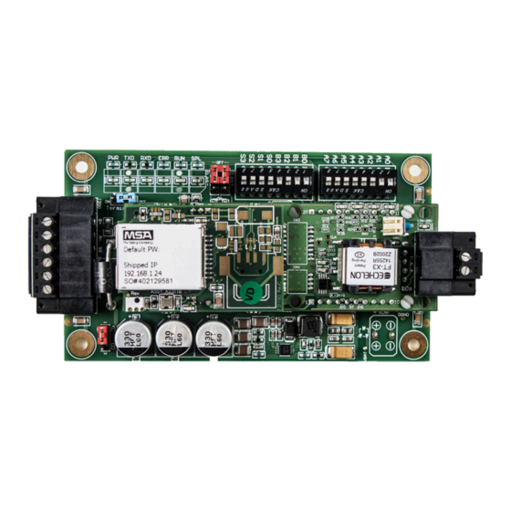
Chapter - 5. Interfacing MCS-BMS-GATEWAY to Devices 5.1. MCS-BMS-GATEWAY Connection Ports Figure 7: MCS-BMS-GATEWAY... -
Page 22: Wiring Diagram For Connecting The Mcs-Magnum
5.2. Wiring diagram for connecting the MCS-Magnum Wire to 12 volt power supply 04-14-2022 BMS Communication Rev. 04-14-2022... -
Page 23: Device Connections To Mcs-Bms-Gateway
5.3. Device Connections to MCS-BMS-GATEWAY MCS-BMS-GATEWAY6 Pin Phoenix connector for RS-485 Devices. • Pins 1 through 3 are for RS-485 devices. • The RS-485 GND (Pin 3) is not typically connected • Pins 4 through 6 are for power. Do not connect power (wait until Section 3.4). MCS-BMS-GATEWAY- Device Pins Pin Assignment... - Page 24 from MCS-Magnum’s keypad the keypad/LCD of a live unit. To get authorized on Magnum do the following: Press ‘Menu’ Using , , , or position curser to ‘Passwords’ Press key. Enter 4 digit password & press . Press ‘Menu’...
-
Page 25: Biasing The Rs-485 Device Network
bers and use , to increase and decrease the second value and repeat the previous steps for rest of the ip address. 11. Once you have set the desired address press the Enter key. 12. Reset or cycle power to the magnum for the change to take effect. The MCS-MAGNUM IP address can be verified and changed (with the proper authorization code) from MCS-CONNECT of a live unit. -
Page 26: Power-Up Mcs-Bms-Gateway
• On long RS-485 cabling runs, the RS-485 trunk must be properly terminated at each end. • The MCS-BMS-GATEWAY has an End of Line (EOL) blue jumper. The default setting for this Blue EOL switch is OFF with the jumper straddling the pins closest to the inside of the board of the MCS-BMS-GATEWAY. -
Page 27: Chapter - 6. Mcs-Bms-Gateway-N54 Start-Up Guide
Chapter - 6. MCS-BMS-GATEWAY-N54 START-UP GUIDE Start-up Guide MCS-BMS GATEWAY- N54... - Page 28 Description About the ProtoNode ProtoNode is a high performance, cost effective Building and Industrial Automation multi-protocol gateway providing protocol translation between serial/Ethernet devices and networks. NOTE: For troubleshooting assistance refer to Section 9, or any of the troubleshooting appendices in the related driver supplements. Check the MSA Safety website for technical support resources and documentation that may be of assistance.
- Page 29 Equipment Setup Equipment Setup Mounting The ProtoNode can be mounted using the DIN rail mounting bracket on the back of the unit. Din Rail Bracket Figure 1: DIN Rail Bracket ProtoNode Start-up Guide...
- Page 30 Equipment Setup Physical Dimensions Power Port R2 Serial Port R1 Serial Port Figure 2: ProtoNode FPC-N54 Dimensions ProtoNode Start-up Guide...
- Page 31 Installing the Gateway Installing the ProtoNode DIP Switch Settings 3.1.1 Bias Resistors R1 Bias Resistor DIP Switches (2 and 3) R2 Bias Resistor DIP Switches (2 and 3) Figure 3: Bias Resistor DIP Switches To enable Bias Resistors, move both the BIAS- and BIAS+ dip switches to the right in the orientation shown in Figure The ProtoNode bias resistors are used to keep the RS-485 bus to a known state, when there is no...
- Page 32 Installing the Gateway 3.1.2 Termination Resistor R1 Termination Resistor DIP Switch (1) R2 Termination Resistor DIP Switch (1) Figure 4: Termination Resistor DIP Switch If the ProtoNode is the last device on the serial trunk, then the End-Of-Line Termination Switch needs to be enabled.
- Page 33 Installing the Gateway Connecting the R1 & R2 Ports For the R1 Port only: Switch between RS-485 and RS-232 by moving the number 4 DIP Switch left for RS-485 and right for RS-232 (Figure The R2 Port is RS-485. Connect to the 3-pin connector(s) as shown below. TX+ RX- GND Figure 5: R1 &...
- Page 34 Power up Power up the ProtoNode Check power requirements in the table below: Power Requirement for ProtoNode External Gateway Current Draw Type ProtoNode Family 12VDC 24VDC/AC FPC – N54 (Typical) 250mA 125mA NOTE: These values are ‘nominal’ and a safety margin should be added to the power supply of the host system.
- Page 35 Connecting to the Gateway Connect the PC to the ProtoNode Connecting to the Gateway via Ethernet Connect a Cat-5 Ethernet cable (straight through or cross-over) between the local PC and ProtoNode. Ethernet Port Figure 8: Ethernet Port Location 5.1.1 Changing the Subnet of the Connected PC The default IP Address for the ProtoNode is 192.168.2.101, Subnet Mask is 255.255.255.0.
- Page 36 Setup Web Server Security Setup Web Server Security Login to the FieldServer The first time the FieldServer GUI is opened in a browser, the IP Address for the gateway will appear as untrusted. This will cause the following pop-up windows to appear. When the Web Server Security Unconfigured window appears, read the text and choose whether •...
- Page 37 Setup Web Server Security • Additional text will expand below the warning, click the underlined text to go to the IP Address. In Figure 11 example this text is “Proceed to 10.40.50.94 (unsafe)”. Figure 11: Warning Expanded Text • When the login screen appears, put in the Username (default is “admin”) and the Password (found on the label of the FieldServer).
- Page 38 Setup Web Server Security Select the Security Mode On the first login to the FieldServer, the following screen will appear that allows the user to select which mode the FieldServer should use. Figure 13: Security Mode Selection Screen NOTE: Cookies are used for authentication. NOTE: To change the web server security mode after initial setup, go to Section 10.2.
- Page 39 Setup Web Server Security Select the Security Mode On the first login to the FieldServer, the following screen will appear that allows the user to select which mode the FieldServer should use. Figure 13: Security Mode Selection Screen NOTE: Cookies are used for authentication. NOTE: To change the web server security mode after initial setup, go to Section 10.2.
- Page 40 Setup Web Server Security 6.2.1 HTTPS with Own Trusted TLS Certificate This is the recommended selection and the most secure. Please contact your IT department to find out if you can obtain a TLS certificate from your company before proceeding with the Own Trusted TLS Certificate option.
- Page 41 Configuring the Gateway Network Settings Using FS-GUI to Input Network Settings To navigate from the FS-GUI page to the Network Settings page follow the below instructions: Find the Navigation tree across the left side of the screen. • Click the orange arrow next to the ProtoNode CN number and title to expand the tree. •...
- Page 42 Configuring the Gateway Routing Settings The Routing settings make it possible to set up the IP routing rules for the FieldServer’s internet and network connections. Click the Add Rule button to add a new row and set a new Destination Network, Netmask and •...
- Page 43 Configuring the Gateway Ethernet 1 Network Settings To change the IP Settings, follow these instructions: • Enable DHCP to automatically assign IP Settings or modify the IP Settings manually as needed, via these fields: IP Address, Netmask, Default Gateway, and Domain Name Server1/2. NOTE: If the FieldServer is connected to a router, the IP Gateway of the FieldServer should be set to the same IP Address of the router.
- Page 44 Configuring the Gateway Configuring the ProtoNode Retrieve the Sample Configuration File The configuration of the ProtoNode is provided to the ProtoNode’s operating system via a comma-delimited file called “CONFIG.CSV”. If a custom configuration was ordered, the ProtoNode will be programmed with the relevant device registers in the Config.csv file for the initial start-up.
- Page 45 Configuring the Gateway Load the Updated Configuration File 8.3.1 Using the FS-GUI to Load a Configuration File • In the main menu of the FS-GUI screen, click “Setup”, then “File Transfer” and finally “Update”. • Browse and select the .csv file, open, then click “Submit”. Figure 20: FS-GUI Loading Files •...
- Page 46 Configuring the Gateway 8.3.2 Retrieve the Configuration File for Modification or Backup To get a copy of the configuration file for modifying or backing up a configuration on a local computer, do the following: In the main menu of the FS-GUI screen, click “Setup”, then “File Transfer”. •...
- Page 47 Configuring the Gateway Test and Commission the ProtoNode • Connect the ProtoNode to the third party device(s), and test the application. • From the landing page of the FS-GUI click on “View” in the navigation tree, then “Connections” to see the number of messages on each protocol. Figure 22: FS-GUI Connections Screen NOTE: For troubleshooting assistance refer to Section 9, or any of the troubleshooting appendices in the related driver supplements and configuration manual.
- Page 48 Troubleshooting Troubleshooting Lost or Incorrect IP Address • Ensure that FieldServer Toolbox is loaded onto the local PC. Otherwise, download the FieldServer-Toolbox.zip via the MSA Safety website. Extract the executable file and complete the installation. • Ethernet Port Figure 23: Ethernet Port Location •...
- Page 49 Troubleshooting Viewing Diagnostic Information • Type the IP Address of the ProtoNode into the web browser or use the FieldServer Toolbox to connect to the ProtoNode. • Click on Diagnostics and Debugging Button, then click on view, and then on connections. If there are any errors showing on the Connection page, refer to Section for the relevant wiring •...
- Page 50 Troubleshooting Checking Wiring and Settings No COMS on the Serial side. If the Tx/Rx LEDs are not flashing rapidly then there is a COM issue. To fix this problem, check the following: • Visual observations of LEDs on the ProtoNode. (Section 9.5) •...
- Page 51 Troubleshooting Taking a FieldServer Diagnostic Capture When there is a problem on-site that cannot easily be resolved, perform a Diagnostic Capture before contacting support. Once the Diagnostic Capture is complete, email it to technical support. The Diagnostic Capture will accelerate diagnosis of the problem. If the FieldServer bios is updated/released on November 2017 or later then the Diagnostic Capture is performed via the gateway’s on-board system.
- Page 52 Troubleshooting LED Functions FPC-N54 Diagnostic LEDs Description The SS LED will flash once a second to indicate that the bridge is in operation. The SYS ERR LED will go on solid indicating there is a system error. If this occurs, immediately report the related “system error”...
- Page 53 Troubleshooting Factory Reset Instructions For instructions on how to reset a FieldServer back to its factory released state, see ENOTE - FieldServer Next Gen Recovery. Internet Browser Software Support The following web browsers are supported: Chrome Rev. 57 and higher •...
-
Page 54: Chapter - 7. Bms Switch Settings
Chapter - 7. BMS SWITCH SETTINGS 7.1. BMS Address DIP Switch Settings Address... - Page 55 Address...
- Page 56 Address...
- Page 57 Address...
- Page 58 Address...
- Page 59 Address...
-
Page 60: Chapter - 8. Appendix - Input / Output Points / States
Chapter - 8. APPENDIX - INPUT / OUTPUT POINTS / STATES 8.1. Sensor Input Points Sensor numbering is based upon the MCS-MAGNUM or SI16-AO4 (SI-Base and SI-EXT) hardware type board Nota- ble BACnet properties available: Units BACnet Modbus BACnet Modbus Magnum BACnet Name Magnum... -
Page 61: Relay Output Points
8.2. Relay Output Points Relay Output points are read-only. Output numbering is based upon MCS-RO-10 (MCS-RO BASE, MCS-RO-EXT) hard- ware type board. Magnum BACnet ID BACnet Name Modbus Magnum BACnet ID BACnet Name Modbus Relay M–1 BO: 1 Refer to Config 00001 BO: 1 Relay 4–1... -
Page 62: Analog Output Points
8.3. ANALOG Output Points Analog Output Points are read-only. Output numbering is based upon SI16-AO4 (SI-Base and SI-EXT) hardware type board. Notable BACnet properties available: Units Magnum BACnet ID BACnet Name Modbus Register Analog Out M-1 AO:1 Refer to Config *30201 *AO: 1 Analog Out M-2... -
Page 63: Other Points
Magnum BACnet ID BACnet Name Modbus Register Compressor #3 State MV:3 COMPRESSOR #3 STATE 30309 BYT:4 Compressor #4 State MV:4 COMPRESSOR #4 STATE 30310 BYT:5 Compressor #5 State MV:5 COMPRESSOR #5 STATE 30311 BYT:6 Compressor #6 State MV:6 COMPRESSOR #6 STATE 30312 BYT:7 Compressor #7 State... - Page 64 Magnum BACnet ID BACnet Name Modbus Compressor #4 Disch SH AV:33 C4_Disch SH *30342 *ADF:34 Compressor #4 Suct SH AV:34 C4_Suct SH *30340 *ADF:35 Compressor #4 Oil Pres Diff AV:66 C4_Oil Pres Diff *30378 *ADF:67 Compressor #5 FLA% AV:35 C5_FLA% *30323 *ADF:36 Compressor #5 Sat Suction...
- Page 65 Magnum BACnet ID BACnet Name Modbus Compressor #13 FLA% AV:468 C13_FLA% *30576 *ADF:469 Compressor #13 Sat Suction AV: 471 C13_Sat Suct *30600 *ADF: 470 Compressor #13 Sat Disch AV: 472 C13_ Sat Disch *30602 *ADF: 473 Compressor #13 Disch SH AV: 473 C13_Disch SH *30603...
-
Page 66: Network Inputs To Mcs-Magnum
8.7. Network inputs to MCS-MAGNUM The MCS-Magnum can receive changes from the network to enable or disable the Network Run/Stop, Network Target Reset (adjustments to the Cooling Target, Setpoint #1, based on Setpoint #21), Network Demand FLA, and Network Demand Steps. The MCS-Magnum must be set up to accept these inputs. -
Page 67: Mcs Capacity Control State Chart
8.8. MCS Capacity Control State Chart The values exposed in the capacity state relate to the descriptions in this table. RESERVED State Number Description “AMBIENT OFF “ “UNIT IN POWER UP” “PROCESS HEAT OFF” RESERVED “UNIT IS UNLOADED” “NO RUN- I/O LOST” “UNIT IS LOADED “... -
Page 68: Chapter - 9. Alarms- Unit/Compressor / Modbus
Chapter - 9. ALARMS- UNIT/COMPRESSOR / MODBUS 9.1. Unit Alarms Modbus Info BACnet Object Identifier V17 Frimware BACnet Object Relay Unit Alarms Function Type Register Address Modbus BACnet Type output EMERGENCY_STOP 04:input Register 31011 AV: Ananlog Value 1296 HVAC//RTU HVAC//RTU HVAC//RTU FREEZE_PROTECTION 04:input Register... -
Page 69: Compressor Alarms
9.2. Compressor Alarms V17 Frimware Supporting Alarm Indicators Compressor Alarms Relay output Modbus BACnet LOW_SUCTION HVAC/RTU HVAC/RTU HVAC/RTU UNSAFE_SUCTION HVAC/RTU HVAC/RTU HVAC/RTU HIGH_DISCHARGE_PSI HVAC/RTU HVAC/RTU HVAC/RTU HIGH_DISCHARGE_TEMP HVAC/RTU HVAC/RTU HVAC/RTU LOW_OIL_PSI HVAC/RTU HVAC/RTU HVAC/RTU UNSAFE_OIL_PSI HVAC/RTU HVAC/RTU HVAC/RTU HIGH_OIL_TEMP HVAC/RTU HVAC/RTU HVAC/RTU DIRTY_OIL_FILTER... - Page 70 V17 Frimware Supporting Alarm Indicators Compressor Alarms Relay output Modbus BACnet Discharge Temperature Sensor Fault HVAC/RTU HVAC/RTU HVAC/RTU Suction Pressure Sensor Fault HVAC/RTU HVAC/RTU HVAC/RTU Discharge Pressure Sensor Fault HVAC/RTU HVAC/RTU HVAC/RTU Oil Pressure Sensor Fault HVAC/RTU HVAC/RTU HVAC/RTU Oil Temperature Sensor Fault HVAC/RTU HVAC/RTU HVAC/RTU...
-
Page 71: Modbus Alarms
9.3. MODBUS Alarms... -
Page 76: Chapter - 10. Creating Csv Files Using Mcs-Config
Chapter - 10. CREATING CSV FILES USING MCS-CONFIG 9.4. How to Create CSV Files: 1. Open MCS-Config program and load the config you are working on. 2. Click on Setup. 3. Be sure to set IP Address, Subnet Mask, Default Gateway, MCS IP Port and Bacnet Device ID, then save config file. - Page 77 6. When popup window comes up click ok. 7. When prompted, select the file location where you want to save the csv files. This would be the time to name the CSV files, there is a 15 character maximum not including the file extension. If you do not name the file it will default to the first 15 characters of the config name.
- Page 78 Providing HVAC/R Control Solutions Worldwide 5580 Enterprise Pkwy. Fort Myers, FL 33905 Office: (239) 694-0089 Fax: (239) 694-0031 www.mcscontrols.com...
Need help?
Do you have a question about the MCS-BMS-GATEWAY-see and is the answer not in the manual?
Questions and answers