Table of Contents
Advertisement
Advertisement
Table of Contents

Subscribe to Our Youtube Channel
Related Manuals for Hewlett Packard Enterprise aruba AP-504


Summary of Contents for Hewlett Packard Enterprise aruba AP-504
- Page 1 Aruba AP-504, AP-505, AP-514, AP- 515, AP-534, AP-535 and AP-555 Wireless Access Points with ArubaOS FIPS Firmware Non-Proprietary Security Policy FIPS 140-2 Level 2 Version 1.1 February 2021 Aruba AP-5XX Wireless Access Points with ArubaOS FIPS Firmware FIPS 140-2 Level 2 Security Policy...
- Page 2 . All rights reserved. All other trademarks are the property of their respective owners. Open Source Code Certain Hewlett Packard Enterprise Company products include Open Source software code developed by third parties, including software code subject to the GNU General Public License (GPL), GNU Lesser General Public License (LGPL), or other Open Source Licenses.
-
Page 3: Table Of Contents
Contents Purpose of this Document ............................ 7 1.1. Related Documents............................7 1.2. Additional Product Information ........................7 1.3. Acronyms and Abbreviations ........................8 Overview ................................9 AP-500 Series ..............................9 2.1.1 Physical Description ..........................11 2.1.2 Dimensions/Weight ..........................11 2.1.3 Environmental ............................. - Page 4 11.2. Identifying Specific Installation Locations....................39 11.3. Precautions ............................. 40 11.4. Product Examination ..........................40 11.5. Package Contents ............................ 40 Tamper-Evident Labels ........................... 41 12.1. Reading TELs ............................41 12.2. Required TEL Locations ........................... 42 12.2.1 TELs Placement on the AP-504 ......................42 12.2.2 TELs Placement on the AP-505 ......................
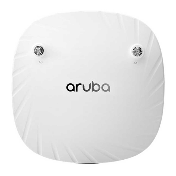
- Page 5 Figures Figure 1 - Aruba AP-504 Campus Access Point – Front ....................9 Figure 2 - Aruba AP-504 Campus Access Point – Back ....................9 Figure 3 - Aruba AP-505 Campus Access Point – Front ....................10 Figure 4 - Aruba AP-505 Campus Access Point – Back ....................10 Figure 5 - Aruba AP-500 Series Campus Access Point –...
- Page 6 Tables Table 1 - AP-500 Series Status Indicator LEDs ......................12 Table 2 - AP-510 Series Status Indicator LEDs ......................16 Table 3 - AP-530 Series Status Indicator LEDs ......................20 Table 4 - AP-550 Series Status Indicator LEDs ......................23 Table 5 - Intended Level of Security ...........................
-
Page 7: Purpose Of This Document
In addition, in this document, the Aruba AP-504, AP-505, AP-514, AP-515, AP-534, AP-535 and AP-555 Wireless Access Points are referred to as the Wireless Access Point, the AP, the module, the cryptographic module, Aruba Wireless Access Points, Aruba Wireless APs, Aruba Campus Access Points, and AP-5XX Wireless Access Points. -
Page 8: Acronyms And Abbreviations
1.3. Acronyms and Abbreviations Advanced Encryption Standard Access Point Cipher Block Chaining Command Line Interface Crypto Officer CPSec Control Plane Security protected CSEC Communications Security Establishment Canada Critical Security Parameter External Crypto Officer Electromagnetic Compatibility Electromagnetic Interference Fast Ethernet Gigabit Ethernet Gigahertz HMAC Hashed Message Authentication Code... -
Page 9: Overview
2. Overview This section introduces the Aruba AP-504, AP-505, AP-514, AP-515, AP-534, AP-535 and AP-555 Wireless , providing a brief overview and summary of the physical features of each model covered by this Access Points FIPS 140-2 security policy. The tested version of the firmware is: ArubaOS 8.6.0.7-FIPS. -
Page 10: Figure 3 - Aruba Ap-505 Campus Access Point - Front
Figure 3 - Aruba AP-505 Campus Access Point – Front Figure 4 - Aruba AP-505 Campus Access Point – Back With a maximum concurrent data rate of 1.2 Gbps in the 5 GHz band and 574 Mbps in the 2.4 GHz band (for an aggregate peak data rate of 1.77 Gbps), the 500 Series Wireless Access Points deliver affordable high performance 802.11ax access for mobile and IoT devices in indoor environments where device density is high such as higher education, K12, retail branches, hotels and digital workplaces. -
Page 11: Physical Description
2.1.1 Physical Description The Aruba AP-504 and AP-505 Campus Access Points are multi-chip standalone cryptographic modules consisting of hardware and software, all contained in hard, opaque plastic cases. The modules contain 802.11 a/b/g/n/ac/ax transceivers and support two integrated omni-directional downtilt antennas each. -
Page 12: Figure 5 - Aruba Ap-500 Series Campus Access Point - Interfaces
Figure 5 - Aruba AP-500 Series Campus Access Point – Interfaces DC power interface: 12Vdc nominal, +/- 5% 2.1mm/5.5mm center-positive circular plug with 9.5mm length USB 2.0 host interface (Type A connector) Bluetooth 5.0 Low Energy (BLE5.0) and Zigbee (802.15.4) radio: ... -
Page 13: Ap-510 Series
2.2 AP-510 Series This section introduces the Aruba AP-510 Series Campus Access Points (APs) with FIPS 140-2 Level 2 validation. It describes the purpose of the AP-514 and AP-515 APs, their physical attributes, and their interfaces. Figure 6 - Aruba AP-514 Campus Access Point – Front Figure 7 - Aruba AP-514 Campus Access Point –... -
Page 14: Figure 9 - Aruba Ap-515 Campus Access Point - Back
Figure 9 - Aruba AP-515 Campus Access Point – Back With a maximum concurrent data rate of 4.8 Gbps in the 5 GHz band and 575 Mbps in the 2.4 GHz band (for an aggregate peak data rate of 3 Gbps), the 510 Series Access Points deliver high performance 802.11ax access for mobile and IoT devices in indoor environments for any enterprise environment. -
Page 15: Physical Description
2.2.1 Physical Description The Aruba AP-514 and AP-515 Campus Access Points are multi-chip standalone cryptographic modules consisting of hardware and software, all contained in hard, opaque plastic cases. The modules contain 802.11 a/b/g/n/ac/ax transceivers and support four integrated omni-directional downtilt antennas each. The case physically encloses the complete set of hardware and software components and represents the cryptographic boundary of the module. -
Page 16: Figure 10 - Aruba Ap-510 Series Campus Access Point - Interfaces
Figure 10 - Aruba AP-510 Series Campus Access Point – Interfaces DC power interface: 12Vdc nominal, +/- 5% 2.1mm/5.5-mm center-positive circular plug with 9.5-mm length USB 2.0 host interface (Type A connector) Bluetooth 5.0 Low Energy (BLE5.0) and Zigbee (802.15.4) radio: ... -
Page 17: Ap-530 Series
2.3 AP-530 Series This section introduces the Aruba AP-530 Series Campus Access Points (APs) with FIPS 140-2 Level 2 validation. It describes the purpose of the AP-534 and AP-535 APs, their physical attributes, and their interfaces. Figure 11 - Aruba AP-534 Campus Access Point – Front Figure 12 - Aruba AP-534 Campus Access Point –... -
Page 18: Physical Description
Figure 14 - Aruba AP-535 Campus Access Point – Back With a maximum concurrent data rate of 2.4 Gbps in the 5 GHz band and 1,150 Mbps in the 2.4 GHz band (for an aggregate peak data rate of 3.55 Gbps), the 530 Series Access Points deliver high performance 802.11ax access for mobile and IoT devices in indoor environments for any enterprise environment. -
Page 19: Dimensions/Weight
The case physically encloses the complete set of hardware and software components and represents the cryptographic boundary of the module. The Access Point configuration validated during the cryptographic module testing included: AP-534 HW: AP-534-USF1 (HPE SKU JZ342A) AP-535 HW: AP-535-USF1 (HPE SKU JZ347A) 2.3.2 Dimensions/Weight The AP has the following physical dimensions: ... -
Page 20: Table 3 - Ap-530 Series Status Indicator Leds
DC power interface: 48Vdc nominal, +/- 5% 1.35mm/3.5-mm center-positive circular plug with 9.5-mm length USB 2.0 host interface (Type A connector) Bluetooth 5.0 Low Energy (BLE5.0) and Zigbee (802.15.4) radio: Bluetooth 5.0: up to 8dBm transmit power (class 1) and -95dBm receive sensitivity ... -
Page 21: Ap-550 Series
2.4 AP-550 Series This section introduces the Aruba AP-550 Series Campus Access Points (APs) with FIPS 140-2 Level 2 validation. It describes the purpose of the AP-555 APs, their physical attributes, and their interfaces. Figure 16 - Aruba AP-555 Campus Access Point – Front Figure 17 - Aruba AP-555 Campus Access Point –... -
Page 22: Physical Description
The AP-555 has eight integrated dual-band downtilt omni-directional antennas for 4x4 MIMO in 2.4 GHz with peak antenna gain of 4.3 dBi and 8x8 MIMO in 5 GHz with peak antenna gain of 5.8 dBi. Built-in antennas are optimized for horizontal ceiling mounted orientation of the AP. -
Page 23: Figure 18 - Aruba Ap-550 Series Campus Access Point - Interfaces
802.11a/b/g/n/ac/ax eight internal antenna (AP-555) Figure 18 - Aruba AP-550 Series Campus Access Point – Interfaces DC power interface: 48Vdc nominal, +/- 5% 1.35mm/3.5-mm center-positive circular plug with 9.5-mm length USB 2.0 host interface (Type A connector) Bluetooth 5.0 Low Energy (BLE5.0) and Zigbee (802.15.4) radio: ... -
Page 24: Module Objectives
This section describes the assurance levels for each of the areas described in the FIPS 140-2 Standard. 3.1. Security Levels The Aruba AP-504, AP-505, AP-514, AP-515, AP-534, AP-535 and AP-555 Wireless Access Points and associated modules are intended to meet overall FIPS 140-2 Level 2 requirements as shown in Table 3. -
Page 25: Physical Security
(on the bottom of the device) port To protect the Aruba AP-504, AP-505, AP-514, AP-515, AP-534, AP-535 and AP-555 Wireless Access Points from any tampering with the product, TELs should be applied by the Crypto Officer as covered under section 12, Tamper-Evident Labels. -
Page 26: Roles, Authentication And Services
Data input and output, control input, status output, and power interfaces are defined as follows: Data input and output are the packets that use the networking functionality of the module. Control input consists of manual control inputs for power and reset through the power interfaces (power supply or POE). -
Page 27: Table 7 - Crypto-Officer Services
Table 7 - Crypto-Officer Services CSP/Algorithm Access (please Service Description Input Output Table 12 below for details) FIPS mode The CO enables FIPS mode by Commands and Status of None enable/disable following the procedures under configuration data commands and Section 13 to ensure the AP is configuration data configured for Secure Operations. -
Page 28: User Role
Table 7 - Crypto-Officer Services the wired network. Openflow Agent Agent run on device for use with Configuration Data and Status of None Mobility Master SDN. Leveraged statistic collection commands and by the SDN for discovering of configuration data hosts and networks, configuration of networks, and collection of statistics. -
Page 29: Unauthenticated Services
Table 8 - Estimated Strength of Authentication Mechanisms Therefore the associated probability of a successful random attempt during a one-minute period is 60,000/2^128, which is less than 1 in 100,000 required by FIPS 140-2. Unauthenticated Services The module provides the following unauthenticated services, which are available regardless of role. ... -
Page 30: Cryptographic Key Management
8. Cryptographic Key Management 8.1. FIPS Approved Algorithms The firmware in each module contains the following cryptographic algorithm implementations/crypto libraries to implement the different FIPS approved cryptographic algorithms that will be used for the corresponding security services supported by the module in FIPS mode: ... -
Page 31: Table 10 - Arubaos Crypto Module Cavp Certificates
Note: Note: The module implements the power-up self-test service to each of the above algorithms that are supported by ArubaOS OpenSSL Module algorithm implementation. Except for DRBG (Cert. #C1253) called by cryptographic key generation, the module doesn't use the rest of the algorithms in other Approved security services at this time. -
Page 32: Table 11 - Arubaos Uboot Bootloader Cavp Certificates
AES-CBC HMAC-SHA-1, HMAC-SHA2-256, 128, 192, 256 C1254 HMAC-SHA2-384 Key Wrapping/Key Transport HMAC SP 800-38F Key Size < Block via IKE/IPSec HMAC-SHA-1-96, C1254 Size HMAC-SHA-256- 128, HMAC-SHA- 384-192 Table 11 - ArubaOS UBOOT Bootloader CAVP Certificates ArubaOS UBOOT Bootloader CAVP Key Lengths, Algorithm Standard Mode/Method... -
Page 33: Non-Fips Approved But Allowed Cryptographic Algorithms
8.2. Non-FIPS Approved but Allowed Cryptographic Algorithms The cryptographic module implements the following non-FIPS Approved algorithms that are Allowed for use in the FIPS 140-2 mode of operations: NDRNG (used solely to seed the Approved DRBG) Diffie-Hellman (key agreement; key establishment methodology provides 112 bits of encryption strength) ... -
Page 34: Critical Security Parameters
9. Critical Security Parameters The following are the Critical Security Parameters (CSPs) used in the module (unless explicitly specified, a CSP is applicable to all approved modes of operation). The user is responsible for zeroizing all CSPs when switching modes. Table 12 - CSPs/Keys Used in the Module Algorithm / Name... - Page 35 Table 12 - CSPs/Keys Used in the Module Diffie-Hellman Diffie-Hellman Established during Diffie- Stored in SDRAM Zeroized by rebooting Shared Secret Group 14 Hellman Exchange. Used for memory (plaintext). the module. deriving IPSec/IKE (2048 bits) cryptographic keys. EC Diffie-Hellman EC Diffie-Hellman Generated internally by calling Stored in SDRAM Zeroized by rebooting...
- Page 36 Table 12 - CSPs/Keys Used in the Module IPSec Session AES (CBC) and The IPSec (IKE phase II) Stored in SDRAM Zeroized by rebooting Encryption Key AES-GCM encryption key. This key is memory (plaintext). the module. (128/192/256 bits) derived via a key derivation function defined in SP800-135 KDF (IKEv2).
-
Page 37: Self-Tests
Notes: AES GCM IV generation is performed in compliance with the Implementation Guidance A.5 scenario 1. The module is compliant with RFC 4106 and 7296. Specifically, the module uses RFC 7296 compliant IKEv2 to establish the shared secret SKEYSEED from which the AES GCM encryption keys are derived. ... - Page 38 The module performs the following Conditional Tests: ArubaOS OpenSSL Module algorithm implementation: CRNG Test on Approved DRBG CRNG Test for NDRNG ECDSA Pairwise Consistency Test RSA Pairwise Consistency Test SP800-90A Section 11.3 Health Tests for CTR_DRBG (Instantiate, Generate and Reseed) ...
-
Page 39: Installing The Wireless Access Point
11. Installing the Wireless Access Point This chapter covers the physical installation of the AP-504, AP-505, AP-514, AP-515, AP-534, AP-535 and AP-555 Wireless Access Points with FIPS 140-2 Level 2 validation. The Crypto Officer is responsible for ensuring that the following procedures are used to place the Wireless Access Point in a FIPS-Approved mode of operation. -
Page 40: Precautions
11.3. Precautions All Aruba access points should be professionally installed by an Aruba-Certified Mobility Professional (ACMP). Electrical power is always present while the device is plugged into an electrical outlet. Remove all rings, jewelry, and other potentially conductive material before working with this product. ... -
Page 41: Tamper-Evident Labels
12. Tamper-Evident Labels After testing, the Crypto Officer must apply Tamper-Evident Labels (TELs) to the Wireless Access Point. When applied properly, the TELs allow the Crypto Officer to detect the opening of the device, or physical access to restricted ports (i.e. the serial console port on the bottom of each AP-5XX). Aruba Networks provides FIPS 140 designated TELs which have met the physical security testing requirements for tamper evident labels under the FIPS 140-2 Standard. -
Page 42: Required Tel Locations
12.2. Required TEL Locations This section displays the locations of all TELs on each module (AP-504, AP-505, AP-514, AP-515, AP-534, AP-535 and AP-555 Wireless Access Points). Refer to the next section for guidance on applying the TELs. 12.2.1 TELs Placement on the AP-504 The AP-504 requires 4 TELs: one on each side edge (labels 1, 2 and 3) to detect opening the device and one covering the console port (label 4) to detect access to a restricted port. -
Page 43: Tels Placement On The Ap-505
12.2.2 TELs Placement on the AP-505 The AP-505 requires 4 TELs: one on each side edge (labels 1, 2 and 3) to detect opening the device and one covering the console port (label 4) to detect access to a restricted port. See figures 22 and 23 for placement. Figure 22 –... -
Page 44: Tels Placement On The Ap-514
12.2.3 TELs Placement on the AP-514 The AP-514 requires 3 TELs: one on each side edge (labels 1 and 2) to detect opening the device and one covering the console port (label 3) to detect access to a restricted port. See figures 24 and 25 for placement. Figure 24 –... -
Page 45: Tels Placement On The Ap-515
12.2.4 TELs Placement on the AP-515 The AP-515 requires 4 TELs: one on each side edge (labels 1, 2 and 3) to detect opening the device and one covering the console port (label 4) to detect access to a restricted port. See figures 26 and 27 for placement. Figure 26 –... -
Page 46: Tels Placement On The Ap-534
12.2.5 TELs Placement on the AP-534 The AP-534 requires 3 TELs: one on each side edge (labels 1 and 2) to detect opening the device and one covering the console port (label 3) to detect access to a restricted port. See figures 28 and 29 for placement. Figure 28 –... -
Page 47: Tels Placement On The Ap-535
12.2.6 TELs Placement on the AP-535 The AP-535 requires 3 TELs: one on each side edge (labels 1 and 2) to detect opening the device and one covering the console port (label 3) to detect access to a restricted port. See figures 30 and 31 for placement. Figure 30 –... -
Page 48: Tels Placement On The Ap-555
12.2.7. TELs Placement on the AP-555 The AP-555 requires 3 TELs: one on each side edge (labels 1 and 2) to detect opening the device and one covering the console port (label 3) to detect access to a restricted port. See figures 32 and 33 for placement. Figure 32 –... -
Page 49: Applying Tels
12.3. Applying TELs The Crypto Officer should employ TELs as follows: Before applying a TEL, make sure the target surfaces are clean and dry. Clean with alcohol and let dry. Do not cut, trim, punch, or otherwise alter the TEL. ... -
Page 50: Secure Operation
13. Secure Operation The Aruba AP-504, AP-505, AP-514, AP-515, AP-534, AP-535 and AP-555 Wireless Access Points meet FIPS 140-2 Level 2 requirements. The information below describes how to keep the Wireless Access Point in a FIPS- Approved mode of operation. -
Page 51: Crypto Officer Management
13.3. Setup and Configuration The Aruba AP-504, AP-505, AP-514, AP-515, AP-534, AP-535 and AP-555 Wireless Access Points meet FIPS 140-2 Security Level 2 requirements. The sections below describe how to place and keep the Wireless Access Point in a FIPS-Approved mode of operation. -
Page 52: Setting Up Your Wireless Access Point
13.4. Setting Up Your Wireless Access Point The Crypto Officer shall perform the following steps to ensure the APs are placed in the secure operational state: 1. Review the Aruba AP Software Quick Start Guide. Select the deployment scenario that best fits your installation and follow the scenario’s deployment procedures. -
Page 53: Non-Approved Fips Mode Configurations
To verify that FIPS mode has been enabled, issue the command “show fips”. If logging in to the staging controller via the Mobility Master, please reference the ArubaOS 8.6 User Guide on how to access a managed device. Once connected to the staging controller, the above commands will successfully execute.
Need help?
Do you have a question about the aruba AP-504 and is the answer not in the manual?
Questions and answers