Advertisement
Quick Links
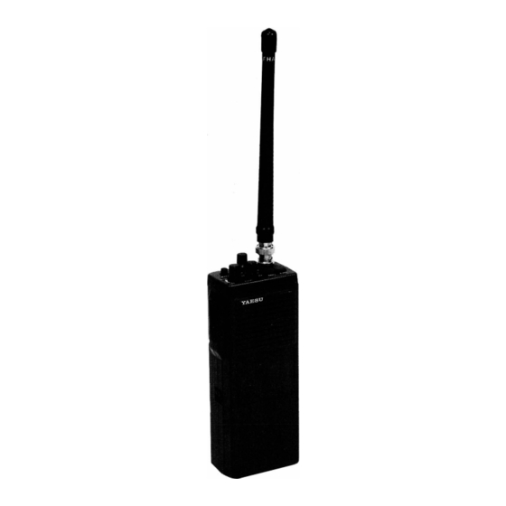
FTH -20 09
SERVICE MANUAL
This booklet contains supplemental technical information
related to the
FTH-2009
Operating Manual. Service or repairs to the FTH-2009
transceiver should be performed by pualified technicians
only.
for use with the
FTH-2009
YAESU MUSEN CO., LTD.
C.P.O.BOX 1500, TOKYO,JAPAN
YAESU U.S.A.
17210 Ebwards Rd. Cerritos, Califorria, 90701 US.A
YAESU EUROPE B. V.
Snipweg 3. 1118AA Schiphol The l'�ETHERLANDS
Advertisement

Related Manuals for Yaesu FTH-2009

Summary of Contents for Yaesu FTH-2009
- Page 1 This booklet contains supplemental technical information related to the FTH-2009 for use with the FTH-2009 Operating Manual. Service or repairs to the FTH-2009 transceiver should be performed by pualified technicians only. YAESU MUSEN CO., LTD. C.P.O.BOX 1500, TOKYO,JAPAN YAESU U.S.A.
- Page 2 Your cooperation in pointing out any inconsistencies in the technical information would be appreciated. Yaesu Musen reserves the right to make changes in the circuitry of this transceiver, in the interest of technological improvement, without notification of the owners.
- Page 3 GENERAL Frequency Coverage: Vers. A 150.8-163 161-174 MHz 136-151 Number of Channels: Up to 6 simplex or semi-duplex Minimum Channel Step: 25 kHz Antenna (BNC Jack): Supplied rubber flex antenna Antenna Impedance: 50 ohms (Unbalanced) Supply Voltage: 6.0 to 12.0 Current Consumption (Approx): Standby 35mA Receive 200mA Transmit 0.8A w/2.5W RF, 1.2A w/4.5W RF...
- Page 4 Make sure the transceiver is off. Remove the Lift the EEPROM Unit (or Matrix Unit) from hard or soft case, if used, and remove the battery the rear side of the chassis to remove it. pack. Disconnect the antenna from the top panel. Pull off the three knobs on the top panel, and EAR/MIC remove the...
- Page 5 ROl31830 R3131760 R7 I 2462Q. R0513800 TX UNIT CP2083001 R0513810 R7131930 R3513820 DIODE MATRIX UNIT EEPROM UNIT R7133900 R3513790 R3131770 ROl31890 ROl33890 R3805620A RO 119430...
- Page 6 Warranty R egistration C ard E2850100 Operating M anual F TH -20 09 F TC -22 03N 70(FTH-2009) V l514190(FTC-2203 N ) Carton l*One of these "WALL CHARGER " will be supplid is per local requirement. ACCESSORIES G 2 0 9 0 3 8 9...
- Page 7 (No.1XXX) RX UNIT NOTCH MC336 005) LA4145(Q 007) 089(Q 008) BASE 2S B793R(Q Obverse view of"Component" side BASE COLLEC TOR 2SC535B(Q I 003) 2SC3355(Q 00 I) 2SC2603E(Q I 004) 2SC2026(Q I 002) A4M(Q 006) 2SC2785F(Q I 009. 0 I I) -6 -...
- Page 8 (No.2XXX) TX UNIT · � · N OTCH MC 120 I 7P(Q2004) NOTCH TC9 I 98P(Q200 I) TC5082PL(Q2002) TC508 I AP(Q2003) COLLECTOR 2SC2026(Q2009) 2SC2407A(Q2012) 2SC2538(Q2013) BASE Obverse view of "Component" side � EMIT TER BASE BA I L4M(Q2006,2008,2020) 2SC2785E(Q20 I 0) CDLLECTDR 2SA952M(Q2016,2021,2022) 2SC2603E(Q2017,2018)
- Page 9 . -------------------------------- (2.0V RX UNIT (3.5V) ¥11 1 001 ·�· (3.5V) .rnrlBµ (OV) (OV) �;: ; �l ' · �� "� " r--------------- (9.5V) (7.5V} 11101n (9.5V) R2021 •oo 2S879aR R10l2 8.2 1/U �g � l ) §.1 g�. "" ·�...
- Page 15 2 0 8 4 K 0 0 1 7 5 3 3 0 C E R A M I C C A P . 3 3 p F 5 0 V 2 0 8 5 K 0 0 1 7 5 3 3 0 C E R A M I C C A P .
- Page 17 2 0 3 3 J 0 2 2 2 5 2 2 1 C A RB O N F I L M R E S . 2 2 0 1 / 6 W 2 0 3 4 J 0 2 2 2 5 2 2 2 C A R B O N F I L M R E S .
- Page 18 (No.4XXX) EEPROM UNIT M50747-C I 8FP(Q400 CA T35C 02K(Q4002) µ PD74HC4066G(Q4004) µ PD4030BG(Q4005) � � � Obverse view of "mixed-component" side Marked Surt RH5VA45AA(Q4003) COLLECTOR BAS E Marked Surface Marked Surface ISSl84 2SC27 I 2GR(Q4006) 0400 I ,4002,4003 4004,4005,4006...
- Page 19 r---------------------------- EEPROM UN I T •P04030BO F3117000A ® PLL DATA (16) 04006 ,,.,. R,058 R4059 l 8) PLL DATA C'019 Q'OOS-3 PLL DATA 0.001 B •PD,03080 (IQ) PLL DATA PLL DATA PLL DATA (12) T)( sv Pll DATA (13) PLL MOOE §�...
- Page 20 E E P R O M U N I T C A 0 1 99 0 0 1 E E P R O M U N I T W C O M P . F 3 1 1 7 0 0 0 A P. C . B . W C O M P .
- Page 21 4 01 5 J 2 4 2 0 5 3 3 3 C H I P R E S. 3 3 K 1 / l O W 4 0 1 6 J 2 4 2 0 5 1 0 2 C H I P R E S .
- Page 22 DIODE MATRIX UNIT (No.3XXX) TC4503BF(Q3001,3002) Obverse view of "mixed-component" side - 21-...
- Page 23 ---------------- ---------------- ----- --------------- ------ r - - - - - - M A T R I U N I T ( N 0 . 3 X X X ) TXSV RXSV C H t RX C H t RX CH2 RX CH3 RX CH4 RX CHS...
- Page 24 D I O D E M A T R I X U N I T ** * ** * C P 2 0 8 1 0 0 1 D i o d e M a t r i x Un i t w / C o m p o n e n t s ( e x c e p t P r o g r a m m i n g D i o d e) F 3 0 7 7 0 0 0 P.C.B.
- Page 27 F T T - 6 F 3 1 1 5 1 0 0 P . C . B . W / 0 C O M P . 0 0 0 1 K 1 0 1 7 6 1 0 2 C E R A M I C C A P . O .
- Page 29 r - - - - - - - - - - - - - - - - - - - - - - - - - - - - - - - - - - - - - - - - - - - - - - - - - - - - - - - - - 1 TX 5V C T C S S - U N I T VR600 1...
- Page 30 C T C S S F T S - 2 0 ** * F 3 1 1 6 1 0 0 P . C . B . W / O C O M P . 6 0 0 1 K 2 2 1 7 0 2 4 3 C H I P C A P .
- Page 31 A : 1 1 4 . 6- 1 29 . 6MHz B • 1 29 . 4- 1 4 1 . 6MH1 C ' 1 39 . 6- 1 52 . 6MHz r - - - - - - - - - - - - - - - 1 I I I M I X T O N E...
- Page 32 A' 1 1 4 6 - 1 2 9 . 611Hz 1 . S 1 29 4- 1 4 C ' 1 39 . 6- 1 52 . 611Hz 1 ST - - - - - - - - - - - - r - - - - - - - - - - - - - - r - - - - - - - - - - - - - - - 1 - - - - - - - -...
- Page 33 2603E ) , the output of which i s rectified b y Receiver D l004 / D l005 t o provide squelch T he input signal from the antenna passes switching. T his squelch control D C (adj us first through a low pass filter on the Tx table by the operator via S q uelch control U nit, and is directed to the Rx U nit by t/r VRlOO l ) triggers a gate within Q l005 to...
- Page 34 lowpass filtered by L 200 1 , L 200 2 , R200 1 , the TX 5V line is activated , biasing Q2020 Q2021 which then b rings R2002 , R20 16 and C2004- 2006 t o D C , w hich switch D200 5 into cond uction.
- Page 35 142 . 500 142 . 50 0 1 5 5 . 450 155 . 450 Yaesu representi ve, or the warranty policy (161-174 KHz) (148-158 KHz) Vers . C Vers . D may be voided .
- Page 36 Level P L L & T RAN SM I T T E R Modulation S et up the test equipment as shown above 1 ) With the transceiver set to alignment Adjust the AF transmitter alignment. channel 3, adj ust generator for supply voltage to 7 .
- Page 37 RX Unit Location Nomenclature Rx RF Ampl i f i e r Q l O O l 2 S C 3 3 5 5 NPN Si T rans i s tor Q 1 0 0 2 2 S C 2 0 2 6 NPN S i Trans i s tor R x 1 s t M i xe r Q 1 0 0 3...
-
Page 38: All Rights Reserved
Co p yright © 1 99 0 N o portion of this manual Yaesu usen Co., Ltd. may be reproduced rights reserved. without the permission of Printed in Ja p an. E2850900(31 2 S -DT) Yaesu Musen Co. , Ltd. - Page 39 Agosto...
Need help?
Do you have a question about the FTH-2009 and is the answer not in the manual?
Questions and answers