Advertisement
Quick Links
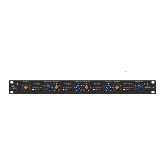
MP312-4 Four Channels Mic Preamp.
Hello DIY lovers!
Thanks for choosing AVDAUDIO!
We are proud to introduce our new MP312-4 Four Channels Mic Preamp.
This unit was made based on vintage API312 version preamp.
Unit has four independent channels. Each channel has:
input gain and output attenuator
phantom power supply bottom +48v
-20Db pad input gain bottom
phase reverse bottom
mute bottom
The box is with external power supply.
If you had bought this DIY Kit, hope this manual help you to complete this
unit. And we hope it will be easy to build and will give you pleasure!
We wish you happy DIY moments with this kit and please contact us at
info@avdaudio.com
Let's start this build!
Assembly Manual
if you have any questions.
©2019
FOUR CHANNELS MIC PREAMP MP312-4
WWW.AVDAUDIO.COM
Advertisement

Related Manuals for AVD Audio MP312-4

Summary of Contents for AVD Audio MP312-4
- Page 1 MP312-4 Four Channels Mic Preamp. Hello DIY lovers! Thanks for choosing AVDAUDIO! We are proud to introduce our new MP312-4 Four Channels Mic Preamp. This unit was made based on vintage API312 version preamp. Unit has four independent channels. Each channel has: ...
- Page 2 FOUR CHANNELS MIC PREAMP MP312-4 • Descriptions and material for building. The MP312-4 DIY kit contains: • Metal case with front panel and power supply case. • PCBs (Main PCB and power supply boards) • Power transformer (115V or 230V included) •...
- Page 3 FOUR CHANNELS MIC PREAMP MP312-4 Ceramic capacitor: IMPORTANT! To avoid any mistakes after the order of the components check each component by multimeter! Make sure that it corresponds to the nominal value indicated on the PCB and place them on a blank sheet with the measured values. Want to remind to you: •...
- Page 4 FOUR CHANNELS MIC PREAMP MP312-4 Preamp PCB has four same channels. All channels are identical. Manual shows building of one channel only. Build other channels by the same way. Others important moment will show you separately. Let’s start main PCB! Solder all resistors and diodes.
- Page 5 FOUR CHANNELS MIC PREAMP MP312-4 Don’t forget about one 10K resistor. It is on the right side of board for power led diode! Find three different ceramic capacitors on the each channel: 120pf, 220pf and two ps of 1000pf. Each capacitor is marked: 120pf capacitors are marked as: ©2019...
- Page 6 FOUR CHANNELS MIC PREAMP MP312-4 220pf capacitors are marked as: 1000pf capacitors are marked as: ©2019 WWW.AVDAUDIO.COM...
- Page 7 FOUR CHANNELS MIC PREAMP MP312-4 Placed each capacitor and solder these: 1000pf capacitor is (two ps): ©2019 WWW.AVDAUDIO.COM...
- Page 8 FOUR CHANNELS MIC PREAMP MP312-4 220pf and 120pf capacitors are placed: Place 4 pushbuttons per each channel on the board: ©2019 WWW.AVDAUDIO.COM...
- Page 9 FOUR CHANNELS MIC PREAMP MP312-4 To be sure before solder! Push button placed directly on the PCB. Must not have any distance from PCB! Turn up board and solder each push button. You can solder at first only one leg of each pushbutton.
- Page 10 FOUR CHANNELS MIC PREAMP MP312-4 Do not recommend cut push button’s legs. For DOA we use HARWIN sockets. ©2019 WWW.AVDAUDIO.COM...
- Page 11 FOUR CHANNELS MIC PREAMP MP312-4 You need one completed DOA. Insert sockets to DOA as I show below: To be sure all sockets are installed fully on DOA! Install this to PCB. ©2019 WWW.AVDAUDIO.COM...
- Page 12 FOUR CHANNELS MIC PREAMP MP312-4 Pull the sockets on 1mm from PCB. Solder only one leg first! Then solder on the other side. Solder the three far legs. Then solder the rest. Or do as we do below: ©2019 WWW.AVDAUDIO.COM...
- Page 13 FOUR CHANNELS MIC PREAMP MP312-4 ©2019 WWW.AVDAUDIO.COM...
- Page 14 FOUR CHANNELS MIC PREAMP MP312-4 Check our result from other side. Ready to do to next step! Find four T-Pads and four Gain potentiometers: ©2019 WWW.AVDAUDIO.COM...
- Page 15 FOUR CHANNELS MIC PREAMP MP312-4 Install each T-Pad to T-Pad’s place on the board marked T-Pad: Place the potentiometer directly on the PCB! ©2019 WWW.AVDAUDIO.COM...
- Page 16 FOUR CHANNELS MIC PREAMP MP312-4 Check again the distance from PCB. We must have not any distance! Go to the down side and solder T-Pads. Solder first only one leg. During soldering push T-pad. Then you solder other legs. We are not recommend to cut this legs after.
- Page 17 FOUR CHANNELS MIC PREAMP MP312-4 Check you are done right. And all T-Pads are on the board: Hope you have done this step good! ©2019 WWW.AVDAUDIO.COM...
- Page 18 FOUR CHANNELS MIC PREAMP MP312-4 And we are ready to go the next step. Take four Gain potentiometers. This one must to be placed directly on PCB too. Look to the next picture and start solder Gain potentiometers. Install Gain potentiometer to their place marked GAIN: Check please the potentiometer is directly on the PCB and solder this: ©2019...
- Page 19 FOUR CHANNELS MIC PREAMP MP312-4 Break off the locking pin on all potentiometers and T-pads! You need 9ps from 14 black screws. This screws are in the ordered package. Tighten all bolts on back wall and bottom cover. ©2019...
- Page 20 FOUR CHANNELS MIC PREAMP MP312-4 How to looks the case with installed bottom cover: The bottom cover has 7 standoffs for PCB. Near future will install PCB to these places. ©2019 WWW.AVDAUDIO.COM...
- Page 21 FOUR CHANNELS MIC PREAMP MP312-4 Stick rubber feet in each corner on the bottom cover. This will protect your cover from scratches. ©2019 WWW.AVDAUDIO.COM...
- Page 22 FOUR CHANNELS MIC PREAMP MP312-4 But now you need XLR connectors. Four are MALE and FEMALE. See picture below: Install each to their place on PCB. Installation sites have a different mount and you will not confuse them! ©2019 WWW.AVDAUDIO.COM...
- Page 23 FOUR CHANNELS MIC PREAMP MP312-4 In the each input we use FEMALE XLR. In output we use MALE XLR. Install all directly on PCB all XLR. Don’t solder on this step! We need to fix all before soldering! ©2019 WWW.AVDAUDIO.COM...
- Page 24 FOUR CHANNELS MIC PREAMP MP312-4 Install the connector with board into the enclosure as shown: And lower the board to the bottom cover: ©2019 WWW.AVDAUDIO.COM...
- Page 25 FOUR CHANNELS MIC PREAMP MP312-4 Make sure the Board is on the bottom cover racks and all XLR connectors are in the holes: And all the holes on the Board and the cover rack are the same! ©2019 WWW.AVDAUDIO.COM...
- Page 26 FOUR CHANNELS MIC PREAMP MP312-4 Check each side of PCB: ©2019 WWW.AVDAUDIO.COM...
- Page 27 FOUR CHANNELS MIC PREAMP MP312-4 Find the seven bolts in the order as shown: And screw the Board to the bottom cover. ©2019 WWW.AVDAUDIO.COM...
- Page 28 FOUR CHANNELS MIC PREAMP MP312-4 Tighten all bolts. In the order there are also 16 screws for XLRs: ©2019 WWW.AVDAUDIO.COM...
- Page 29 FOUR CHANNELS MIC PREAMP MP312-4 Tighten all screws too on the back side. Solder one leg to the board on each XLR. Solder more than one if you can! ©2019 WWW.AVDAUDIO.COM...
- Page 30 FOUR CHANNELS MIC PREAMP MP312-4 But one will be enough! Solder any convenient leg. We soldered each of the central leg. ©2019 WWW.AVDAUDIO.COM...
- Page 31 FOUR CHANNELS MIC PREAMP MP312-4 Find it in the order the following bolts for mounting the front panel: Take the front panel. ©2019 WWW.AVDAUDIO.COM...
- Page 32 FOUR CHANNELS MIC PREAMP MP312-4 Tighten all bolts on the front panel and front panel: Tighten the nut and washer a few (can to all) T-Pads ©2019 WWW.AVDAUDIO.COM...
- Page 33 FOUR CHANNELS MIC PREAMP MP312-4 We use this on three T-Pads: Now! Remove all bolts from the PCB: ©2019 WWW.AVDAUDIO.COM...
- Page 34 FOUR CHANNELS MIC PREAMP MP312-4 We fixed the PCB using T-pads and XLR connectors. We soldered, on each XLR, one leg, as you remember! This step help us to fix the board into the case. And now we can solder and not think that the board can move!
- Page 35 FOUR CHANNELS MIC PREAMP MP312-4 Find in order next positions in the picture: You need for this step: two of screws, washers, spring washers and nuts. ©2019 WWW.AVDAUDIO.COM...
- Page 36 FOUR CHANNELS MIC PREAMP MP312-4 We soldered wires to power connector before! And now we can install and soldering this to PCB. Install Power XLR into the power hole on the right side on the back. IMPORTANT! Usually I using cut wires from output transformer. I had these before. And will not show how I do this.
- Page 37 FOUR CHANNELS MIC PREAMP MP312-4 On the back side: And on the front side: ©2019 WWW.AVDAUDIO.COM...
- Page 38 FOUR CHANNELS MIC PREAMP MP312-4 To be sure! You use wires on the Power XLR. And lengths of these wires be be enough to solder on PCB! ©2019 WWW.AVDAUDIO.COM...
- Page 39 FOUR CHANNELS MIC PREAMP MP312-4 Be careful! We use the same wire colors as the XLR on the power supply! This will help to connect all the wires correctly! If you have other colors of wires! or they are different (on XLR power supply and preamp)!
- Page 40 FOUR CHANNELS MIC PREAMP MP312-4 For this step you need: Four output transformers: And you will need next: 8 bolts, 16 washers, 8 spring washers and 8 nuts. ©2019 WWW.AVDAUDIO.COM...
- Page 41 FOUR CHANNELS MIC PREAMP MP312-4 One washer I use on the top side of transformer Same for two holes! Same washer I use on the bottom side (two ps between transformer and PCB) ©2019 WWW.AVDAUDIO.COM...
- Page 42 FOUR CHANNELS MIC PREAMP MP312-4 And in the end! Use spring washer on the bottom side of PCB: And lock them with nuts: ©2019 WWW.AVDAUDIO.COM...
- Page 43 FOUR CHANNELS MIC PREAMP MP312-4 Cut each wires of transformer. Be sure! Length of each wire enough to solder to PCB! Check length of each wire before cutting! ©2019 WWW.AVDAUDIO.COM...
- Page 44 FOUR CHANNELS MIC PREAMP MP312-4 Trim excess and long legs. Look how it looks like after soldering! ©2019 WWW.AVDAUDIO.COM...
- Page 45 FOUR CHANNELS MIC PREAMP MP312-4 Be sure! Each color has right place: BROWN and RED wire are here: ©2019 WWW.AVDAUDIO.COM...
- Page 46 FOUR CHANNELS MIC PREAMP MP312-4 For the next step we need four Input transformer. This manual we use our TR2622 input transformers. But if you ordered other transformers! Check you have correct schematic or you to change something on the PCB. Sometimes it could be different Zobel or sometimes without Zobel.
- Page 47 FOUR CHANNELS MIC PREAMP MP312-4 Install input transformer. Be sure! The black dot on the transformer coincides the dot on the PCB! It is the first pin of transformer! Flip the board and solder the input transformer as shows below: ©2019...
- Page 48 FOUR CHANNELS MIC PREAMP MP312-4 How to looks our preamp after this step: We need to solder some capacitors per channel. It is 470uf, 330uf and 10uf capacitor. In the picture below you can see all these capacitors. From left to right side: 470uf, 10uf and 330uf.
- Page 49 FOUR CHANNELS MIC PREAMP MP312-4 Before soldering! Be sure! You have right position of each capacitor! 470uf is in the picture below: 330uf capacitor is bellow: ©2019 WWW.AVDAUDIO.COM...
- Page 50 FOUR CHANNELS MIC PREAMP MP312-4 And 10uf capacitor: Flip the board and solder each legs. Trim excess and long legs! ©2019 WWW.AVDAUDIO.COM...
- Page 51 FOUR CHANNELS MIC PREAMP MP312-4 After soldering capacitors check you have everything done correct. And we need to solder two 100uf power capacitors on the right side of PCB. Near to Power XLR. If you do it with completed case. One capacitor near to us be placed with long legs.
- Page 52 FOUR CHANNELS MIC PREAMP MP312-4 But second one must cut to install on the PCB. Otherwise, it will rest against by legs into the case! PCB is 1,5mm thickness. You must have 2,5mm length legs on capacitor! Not less! Instal this capacitor first: ©2019...
- Page 53 FOUR CHANNELS MIC PREAMP MP312-4 Then instal the second: And soldering all these: ©2019 WWW.AVDAUDIO.COM...
- Page 54 FOUR CHANNELS MIC PREAMP MP312-4 Solder JUMPER to the jumper place: You ordered LED diodes separately. Find this in your order. I will show you how to install this. You need four of RED color (+48V) and one GREEN color for power detection.
- Page 55 FOUR CHANNELS MIC PREAMP MP312-4 Longer leg must be solder to left hole marked as “+” Need to bend LED diode as shown below: The red arrow indicates: longer leg must be on the left side. Insert the diode into the hole on the PCB. Then, insert the diode head into the hole on the front panel.
- Page 56 FOUR CHANNELS MIC PREAMP MP312-4 See picture below: For best result you can press to one leg on the bottom side. And solder other one. It really can help you to install this diode good. See below: ©2019 WWW.AVDAUDIO.COM...
- Page 57 FOUR CHANNELS MIC PREAMP MP312-4 Solder all legs: Disassemble the right side of the preamp as shown in the figure below: ©2019 WWW.AVDAUDIO.COM...
- Page 58 FOUR CHANNELS MIC PREAMP MP312-4 Take Green Led Diode. Bend and install in the same way as the red diode. Solder this one from top side of PCB. Assemble the right side of the preamp again! Or… ©2019 WWW.AVDAUDIO.COM...
- Page 59 FOUR CHANNELS MIC PREAMP MP312-4 At this step we recommend wash the Board! Use only professional detergent or alcohol to wash the boards. We recommend that you completely disassemble the case and remove the Board. Although it is possible to wash and not remove the PCB.
- Page 60 FOUR CHANNELS MIC PREAMP MP312-4 Install the top cover and tighten all bolts: Install the caps on the push buttons: ©2019 WWW.AVDAUDIO.COM...
- Page 61 After the last step! Take the knobs you ordered. Set all control knobs to GAIN and OUTPUT. The MP312-4 Preamp is now complete! Congratulations! Wish you the best recordings with our staff! For comments or recommendations send mail please to: info@avdaudio.com...
Need help?
Do you have a question about the MP312-4 and is the answer not in the manual?
Questions and answers