Table of Contents
Advertisement
Quick Links
Advertisement
Table of Contents

Related Manuals for Laird WW 3001


Summary of Contents for Laird WW 3001
- Page 1 Water-Water Cooler WW 3001 Specification and User Manual Version 2.1...
- Page 2 Laird. All specifications are subject to change without notice. Laird assumes no responsibility and disclaims all liability for losses or damages resulting from use of or reliance on this information. All Laird products are sold subject to the Laird Terms and Conditions of sale (including Laird’s limited warranty) in effect from time to time, a copy of which will be furnished upon request.
-
Page 3: Table Of Contents
Table of Contents Revision History ........................5 1 About this Manual ......................6 1.1 Terms of Guarantee ......................6 1.2 Contact Information ......................7 2 Product Identification ...................... 8 2.1 Unit Specifications ......................8 2.2 Identification Plate ......................8 3 Safety Regulations ......................9 3.1 Hazard classes ......................... - Page 4 11.3 Storing the Unit ......................35 11.4 Disposal ......................... 35 11.5 Disposal of Operating Materials ..................35 11.6 Return of the unit to LAIRD .................... 35 12 Wear Parts and Spare Parts ..................36 12.1 General Information ....................... 36 12.2 Parts Overview ....................... 37 Addendum .........................
-
Page 5: Revision History
Revision History Date Index Reason for Change Name Page 24-Apr-2014 Edom/Gimm 29-jun-2017 Update format H. Sharef 08-Oct-2021 Update format A. Chomat... -
Page 6: About This Manual
This document is the English translation of the original Operation Manual in German language for the Water- Water Cooler WW 3001 (called unit in the following). It is based on German safety regulations. In your country other regulations may apply. -
Page 7: Contact Information
Contact Information If you have questions with respect to this unit please use the contact information given below. Always communicate the following: • Your name and address • Name of contact at your address • Product data as on identification plate: Type of unit, serial number and year of manufacture Visit the website for contact details: www.lairdthermal.com... -
Page 8: Product Identification
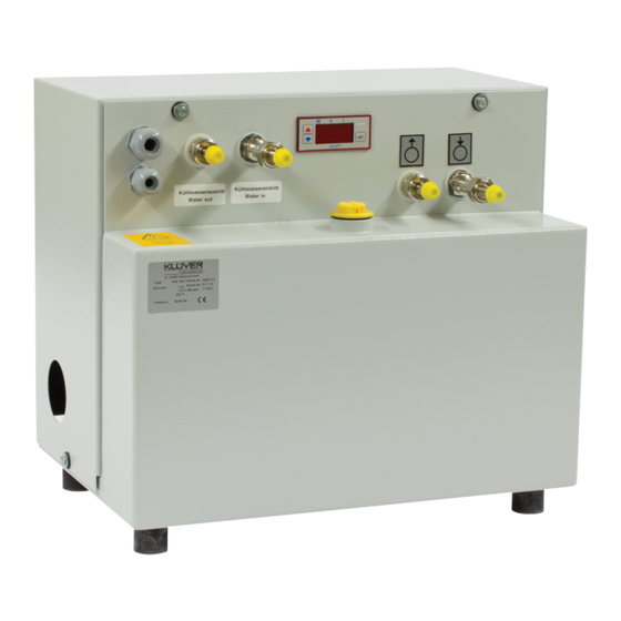
2 Product Identification Unit Specifications Manufacturer Laird Technologies GmbH Type of product Water-water cooler Type of unit WW 3001 Article number 1104.00 Table 1: Unit specifications Identification Plate The identification plate is attached to the front side of the unit (see picture 1). -
Page 9: Safety Regulations
3 Safety Regulations Hazard classes In this document safety instructions are using standardized representation and symbols. Depending on the probability of their incidence and the severances of consequences three hazard classes are used. DANGER Reference to direct danger for humans. Inobservance will lead to irreversible injuries or exitus. -
Page 10: Hints For Safe Operation
Symbol Meaning This symbol indicates the requirement of disconnecting from mains Table 3: Signs giving orders Hints for Safe Operation PLEASE NOTE Conduct inspections on a regular time base. This will ensure that the appropriate measures will actually be carried out. The unit is operational safe. -
Page 11: Hints Regarding The Electrical Equipment
3.3.2 Hints Regarding the Electrical Equipment DANGER Danger to life through electrical shock when working on the electrical equipment of the unit! • Switch-off the unit before starting your work! • Disconnect the unit from mains by pulling the mains plug! •... -
Page 12: Safety Equipment
Safety Equipment PLEASE NOTE The safety equipment listed below must be integrated in the local control environment by the customer, unless otherwise noted. These works must be carried out solely by trained experts. All required information can be taken from the wiring diagram shown in the addendum. Safety equipment must not be modified, removed or taken out of operation. -
Page 13: Guards
3.4.2 Guards Direct access to hazardous parts or areas of the unit is restricted by the unit cover. The cover may only be removed for the purpose of maintenance or repair works and shall be replaced prior to taking the unit back into operation. -
Page 14: In Case Of Accidents
Hint on electrical hazardous area at the back of the unit body In Case of Accidents Should you or another person be injured when working with the unit: • Stay calm • Render first aid • Call the company first-aider without exception... -
Page 15: Product Description
Intended Use The water-water cooler WW 3001 is used for the cooling of a water circuit. As a coolant pure water or a water/antifreeze mixture may be used. The coolant circulates between the cooling unit and the device to be cooled. -
Page 16: Unit Components
Unit Components The unit consists of the following sub-assemblies. Additional information can be retrieved from the flow scheme shown in the addendum. Fig. 6: Main components 1 Coolant container and plate heat exchanger 2 Cooling circuit 3 Body 4.3.1 Functional principle In the cooling circuit the coolant (water or water/glycol) is driven by the pump to the device that is to be cooled and back via the return flow. -
Page 17: Specifications
Specifications Dimensions and weight Length: 450 mm Width: 270 mm Height: 400 mm Weight: 24.0 kg (empty) Coolant contents: 8.5 Liters Table 4: Dimensions and weight Performance data Cooling capacity: 3.0 kW at 5.0 l/min, water at 22°C Throughput: > 5.4 lpm @ 4.0 bars Mains voltage: 230 VAC, 50/60 Hz Current draw:... -
Page 18: Setting-Up Requirements
Setting-up Requirements 4.5.1 Installation Location • The location must be even. • When choosing the installation location, the following must be kept in mind: the air flow of the cooling air for the motor must not be restricted forward and back flow connections must be easily accessible all tubes must be installed without sharp bends 4.5.2 Environmental Conditions... -
Page 19: Transport
Lift the unit with a forklift or jack lift off the transportable pallet. Dispose of the packaging material in accordance with regional regulations. PLEASE NOTE LAIRD advises to keep the transportable pallet and packaging material for later transportation of the unit. -
Page 20: Initial Operation
6 Initial Operation Safety Indications Related to Initial Operation CAUTION Danger of malfunction caused by faulty connections during initial operation! Before switching on the unit make sure that: • All safety equipment of the unit is implemented and functional. • All connections were properly made. Please follow the rules in chapter Safety Regulations on page 9. -
Page 21: Cooling Circuit Connection And Filling
6.2.2 Cooling Circuit Connection and Filling CAUTION Risk of damage by using improper cooling hoses! This may lead to damage to persons, damage to the unit or corrosion damage! • When choosing cooling hoses pay attention to sufficient burst strength and compatibility with coolant! •... -
Page 22: Electrical Connections
Open the coolant container by removing the cap. Fill the coolant container with about 8.5 liters of water or the water/antifreeze mixture. Close the coolant container by fitting the cap. Make sure to use the red cap for operation mode. 6.2.3 Electrical Connections DANGER... -
Page 23: Carrying Out Setting To Work
Remove the back panel after unscrewing the 4 screws. Feed the mains cable through one of the cable bushings and make the connection to the terminal. Then do the same with the wires for the implementation of the safety circuit. Remount the back panel. -
Page 24: Controlling The Unit
7 Controlling the Unit The unit is controlled using the controls of the equipment that is to be cooled. All alarm and error signaling is only indicated on the control panel of the equipment that is to be cooled. Safety Indications for Controlling the Unit CAUTION Lack of coolant may destroy the pump! •... -
Page 25: Settings
7.4.2 By-pass Valve The by-pass valve is set by the manufacturer to a maximum pressure of 2.5 bars. If any modification to this setting should be required, please contact the LAIRD service department to receive briefing. 7.4.3 Temperature Controller To change the temperature values of the water supply (temperature Max P0 or the alarm value (temperature P3) proceed as follows: Fig. - Page 26 7.4.3.1 Water supply - nominal value (P0) set-up Press the SET key for approx. 1 second. ¢ The display shows “P0”. Press the SET key to select P0. ¢ The current temperature setting (factory default value: 25 °C) is displayed. Set-up mode is activated. Use the keys ▲...
- Page 27 7.4.3.3 Setting up the alarm value (P3) for maximum temperature PLEASE NOTE The maximum temperature alarm value is stored in the internal parameter „P3“of the temperature controller. A hysteresis represented by a symmetrical temperature value of 5°C around parameter “P3” has been set between flash-up of the alarm at exceedance of maximum temperature and ceasing of the alarm.
-
Page 28: Disruptions
In the event of fault diagnostics follow the guidelines detailed below: • Only sufficiently qualified personnel may perform maintenance on the unit. • If you cannot determine the error, please contact LAIRD Services. Disruption in Operation The most common reason for disruption in operation of the unit is improper maintenance. Maintenance should be carried out regularly according to the maintenance intervals defined in chapter 9 on page 29. -
Page 29: Trouble Shooting
8.2.1 Trouble Shooting For trouble shooting you may rely on the following: • Alarm signaling within the safety circuit of the device to be cooled • Wiring diagram • Flow scheme • Trouble shooting table given below Problem Possible reasons Countermeasure The unit does not Electrical connection not correct... -
Page 30: Maintenance And Cleaning
9 Maintenance and Cleaning Diligent maintenance is the prime factor for assuring an error-free and efficient operation of the unit. Operating personnel can perform these tasks when properly trained. Maintenance Schedule Device Activity Interval Criteria Tools Performer Coolant container Check filling Weekly Visual inspection Coolant level min. -
Page 31: Cleaning Of Strainer
Cleaning of Strainer Fig. 12: Locations of coolant supply line and strainer 1 Strainer cover 2 Coolant supply line Disconnect the unit from mains. Remove the back panel. CAUTION Some amount of coolant will leak from the pump. It is suggested you put sufficient amount of cloth in a circle underneath the strainer cap location. Remove the strainer cover using a metric AF 24 wrench. -
Page 32: Cleaning Of Unit Body
Cleaning of Unit Body CAUTION Risk of damage through use of improper cleansing material! When using aggressive or abrasive cleaning agents corrosion damage may occur as result of a damaged paint film. • For cleaning the unit body only use mild cleaning agents (e.g.dish washing detergents). •... -
Page 33: Repair
In case of misfunctioning during the warranty period the unit must be sent to the LAIRD service department for repair (see page 7). When warranty has expired, no restrictions from the side of LAIRD exist with respect to repair work carried out by the customer as long as guarantee and warranty conditions remain untouched. -
Page 34: Dismounting, Disposal, Storage
Dismounting, Disposal, Storage 11.1 Temporary Placing out of Operation To take the unit out of operation mode for maintenance, repair or process interruptions proceed as follows: ► Cooling operation is finished. Disconnect the unit from mains. Remove all cabling from the unit. Remove all hoses to and from the unit. -
Page 35: Re-Packaging Of The Unit
The unit was manufactured mainly from recyclable material. Make sure the components of the unit end up at a qualified company for disposal and recycling. Contact LAIRD for taking back end-of-life units (see company contact on page 7 or ask a company specialized in disposal and recycling). -
Page 36: Wear Parts And Spare Parts
Spare parts must comply with the technical specifications defined by LAIRD. Original LAIRD parts are subject to strict obligations and fulfill these requirements. LAIRD does not provide warranty service in case of damages caused by the use of spare parts made by manufacturers other than LAIRD. -
Page 37: Parts Overview
Parts Overview 12.2 Fig. 14: Spare parts overview Pos. Description Article No. Pump 2105.00 Hose fittings (3 parts) 2106.00 Temperature controller 2107.00 Temperature sensor (not shown) Not available Magnet valve 2108.00 Motor 230VAC, 50/60Hz 2001.00 Toothed ring for coupling of pump to motor (not shown) 2038.00 Red operation cap (yellow transport cap shown) 2109.00... -
Page 38: Addendum
Addendum Flow scheme... -
Page 39: Wiring Diagram
Wiring diagram...
Need help?
Do you have a question about the WW 3001 and is the answer not in the manual?
Questions and answers