Table of Contents
Advertisement
Quick Links
ML5 User Manual
Introduction
Welcome to your ML5 Midi Controlled Switcher. This is a MIDI controlled audio loop switcher that enables you to make your non-MIDI-capable
effects part of your midi controller presets, giving you total control of your rig.
Watch
https://youtu.be/9af1pEcpQPo
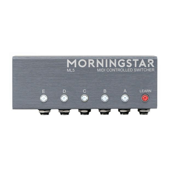
Front Panel
Switches A to E
Each of these switches represent the 5 audio loops available on the ML5. When a switch is lit, the loop is engaged and part of your signal chain.
When a switch is not lit, the loop is bypassed and not in the signal chain.
Learn Button
Press this button to put the ML5 in learn mode. When the Learn button is blinking, the ML5 is in learn mode.
Side Panel
for a video walkthrough and guide.
Advertisement
Table of Contents

Related Manuals for Morningstar ML5

Summary of Contents for Morningstar ML5
- Page 1 Switches A to E Each of these switches represent the 5 audio loops available on the ML5. When a switch is lit, the loop is engaged and part of your signal chain. When a switch is not lit, the loop is bypassed and not in the signal chain.
- Page 2 MIDI Out This is where MIDI messages flow out/thru from the ML5. This allows you to chain the ML5 with other devices. The ML5 does not generate any MIDI messages itself. MIDI In This is where the ML5 receives MIDI messages.
- Page 3 Hold down Switch D before powering up. The ML5 circuit is designed to keep switching noise to a bare minimum. However, you may have certain devices that are more prone to switching noise, such as devices that use an internal charge pump.
- Page 4 Hold down Switch B before powering up. The ML5 can be set to toggle between bypass and active by sending a PC message that engages the currently active loops. For example, if loops A, B, and C are active, and if you send a PC message that is set to engage loops A, B and C, those loops will bypass instead. By default, this setting is disabled.
- Page 5 Mode 2 CC Number Function Values 0-63 Bypasses all loops Values 64-127 Engages all loops. 20 to 24 (corresponds with Loops A to E) Values 0-63 Bypasses the individual loop Values 64-127 Engages the individual loop. 25-29 (corresponds with loops A to E) Any value toggles the individual loop on and off.
Need help?
Do you have a question about the ML5 and is the answer not in the manual?
Questions and answers