Table of Contents
Advertisement
Quick Links
P a g e
| 1
PRODUCT MODEL NUMBER:
TL-9508B TUNER TO IP
GATEWAY
ABOUT THIS
MANUAL
DISCLAIMER
No part of this document may be reproduced in any form without the written permission of the copyright
owner.
The contents of this document are subject to revision without notice due to continued progress in
methodology, design and manufacturing. TRANSLITE GLOBAL LLC shall have no liability for any error or
damage of any kind resulting from the use of this document.
COPY WARNING
This document includes some confidential information. Its usage is limited to the owners of the
product that it is relevant to. It cannot be copied, modified, or translated in another language
without prior written authorization from TRANSLITE GLOBAL LLC
Advertisement
Table of Contents

Subscribe to Our Youtube Channel
Summary of Contents for TransLite TL-9508B
- Page 1 The contents of this document are subject to revision without notice due to continued progress in methodology, design and manufacturing. TRANSLITE GLOBAL LLC shall have no liability for any error or damage of any kind resulting from the use of this document.
-
Page 2: Table Of Contents
P a g e INDEX TABLE OF CONTENTS CHAPTER 1 INTRODUCTION ........................3 1.1 PRODUCT OVERVIEW........................3 1.2 KEY FEATURES........................... 3 1.3 SPECIFICATIONS ..........................4 1.4 PRINCIPLE CHART ..........................6 1.5 APPEARANCE AND DESCRIPTION ...................... 7 CHAPTER 2 INSTALLATION GUIDE ...................... -
Page 3: Chapter 1 Introduction
INTRODUCTION PRODUCT OVERVIEW TL-9508B Tuner to IP Gateway is a head-end interface conversion device which supports MPTS and SPTS output switchable. It supports 16 MPTS or 512 SPTS output over UDP and RTP/RTSP protocol. It is integrated with tuner demodulation (or ASI input) and gateway... -
Page 4: Specifications
P a g e SPECIFICATIONS Input Optional 1:16 tuners input +2 ASI input---SPTS output Optional 2:14 tuners input +2 ASI input --- MPTS output Optional 3:16 tuners input --- MPTS output Tuner Section Standard J.83A(DVB-C), J.83B, J.83C DVB-C Frequency In 30 MHz~1000 MHz Constellation 16/32/64/128/256 QAM... - Page 5 P a g e Frequency In 950-2150MHz QPSK/8PSK /16APSK :0.5~45 Msps Symbol rate 32APSK: 0.5~34Msps; DVB-S2 (Version QPSK: 1/2, 3/5, 2/3, 3/4, 4/5, 5/6, 8/9, 9/10 8PSK: 3/5, 2/3, 3/4, 5/6, 8/9, 9/10 16APSK: 2/3, 3/4, 4/5, 5/6, 8/9, 9/10 32APSK: 3/4, 4/5, 5/6, 8/9, 9/10 Constellation QPSK, 8PSK, 16APSK, 32APSK...
-
Page 6: Principle Chart
P a g e BISS Descrambling Mode 1, Mode E (Up to 850Mbps) (descramble individual program) Miscellaneous Dimension 482mm×410mm×44mm (W×L×H) Approx. weight 3.6kg Environment 0~45℃(work);-20~80℃(Storage) Power requirements 100~240VAC, 50/60Hz Power consumption PRINCIPLE CHART... -
Page 7: Appearance And Description
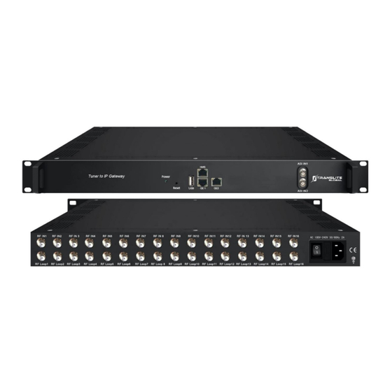
P a g e APPEARANCE AND DESCRIPTION Front Panel Illustration Power indicator Reset: Reset webmaster IP address, recover it to default IP address USB port for upgrade NMS port: Network management interface Data port(GE1&GE2): IP out port ASI input port Rear Panel Illustration... -
Page 8: Chapter 2 Installation Guide
ACQUISITION CHECK When users open the package of the device, it is necessary to check items according to packing list. Normally it should include the following items: ➢ TL-9508B Tuner to IP Gateway User’s Manual ➢ ➢ Grounding Cable ➢... -
Page 9: Device's Installation Flow Chart Illustrated As Following
P a g e DEVICE’S INSTALLATION FLOW CHART ILLUSTRATED AS FOLLOWING Connecting Grouding Connecting Acquisition Installing Setting Running Wire and Signal Check Device Parameter Device Power cable Cord ENVIRONMENT REQUIREMENT Item Requirement When user installs machine frame array in one machine hall, the distance Machine Hall between 2 rows of machine frames should be 1.2~1.5m and the distance Space... -
Page 10: Grounding Requirement
P a g e | 10 GROUNDING REQUIREMENT ➢ All function modules’ good grounding is the basis of reliability and stability of devices. Also, they are the most important guarantee of lightning arresting and interference rejection. Therefore, the system must follow this rule. ➢... -
Page 11: Wire's Connection
When the device adopts united way, the grounding resistance should be smaller than 1Ω. Caution: Before connecting power cord to TL-9508B Tuner to IP Gateway, user should set the power switch to “OFF”. CHAPTER 3... -
Page 12: Login
P a g e | 12 LOGIN ➢ The default IP of this device is 192.168.0.136. ➢ Connect the PC and the device with net cable and use ping command to confirm they are on the same network segment. ➢ I.G. - Page 13 Figure-2 Parameter→ Tuner input (DVB-C/T/T2/ISDBT) From the menu on top side of the webpage, click “Tuner Input”, it displays the interface where users can check the 16 Tuners input status. TL-9508B supports multi tuners switch manually. (Figure-3) Multi tuners input...
- Page 14 P a g e | 14 Clicking “Edit” to set parameters for tuner: DVB-T2 DVB-T DVB-C (J.83A/C)
- Page 15 P a g e | 15 DVB-C (J.83B) ISDB-T Parameter→ ASI input From the menu on top side of the webpage, click “ASI Input”, it displays the interface where users can check the 2 channels of ASI input status. (Figure-4) Figure-4...
- Page 16 P a g e | 16 Parameter→ TS Config Clicking “TS Config”, it displays the interface where users can set the output TS and configure TS ID and ON ID (Figure-5). Figure-5 Parameter→ BISS From the menu on left side of the webpage, clicking “BISS”, it displays the interface where users can configure BISS and descramble the input channels (Figure-6).
- Page 17 P a g e | 17 Parameter → SPTS Select: From the menu on left side of the webpage, clicking “SPTS Select”, it displays the interface where users can choose 16 Tuner input and 2 ASI Input programs to output from IP (max 512 SPTS).
- Page 18 Figure-8 Note: TL-9508B support 16 Tuner input and 2 ASI input with 512 SPTS output, the parameter interface is different from MPTS. When users switch SPTS to MPTS, new mode will work after reboot the device.
- Page 19 From the menu on left side of the webpage, clicking “Program Parse”, it displays the interface where users can parse the program from the input channels. When users disable the ASI input, TL-9508B can support 16 Tuner input with 16 MPTS IP output (Figure-10).
- Page 20 P a g e | 20 When users enable the ASI input, TL-9508B can support 14 Tuner input and 2 ASI input with 16 MPTS IP output (Figure-11). Figure-11 Parameter→ IP Stream TL-9508B supports TS to output in IP (16*MPTS) format through the GE1 or GE2 port. Clicking “IP Stream”, it displays the interface where to set IP out parameters (Figure-12).
- Page 21 P a g e | 21 System → Network: Clicking “Network”, it displays the interface as Figure-13 where to set network parameters. Set NMS IP address, the default IP address is 192.168.0.136 Set GE1 IP address Set GE2 IP address Figure-13 System →...
- Page 22 P a g e | 22 System → Password: From the menu on left side of the webpage, clicking “Password”, it displays the screen as Figure-15 where to set the login account and password for the web NMS. Figure-15 System → Save/Restore: From the menu on left side of the webpage, clicking “Save/Restore”, it displays the screen as Figure-16 where to save or restore your configurations.
- Page 23 P a g e | 23 System → Backup/Load: From the menu on left side of the webpage, clicking “Backup/Load”, it displays the screen as Figure-17 where to backup or load your configurations. Figure-17 System → Firmware: From the menu on left side of the webpage, clicking “Firmware”, it displays the screen as Figure-18 where to update firmware for the device.
-
Page 24: Chapter 4 Troubleshooting
CHAPTER 4 TROUBLESHOOTING All TRANSLITE products have been passed the testing and inspection before shipping out from factory. The testing and inspection scheme already covers all the Optical, Electronic and Mechanical criteria which have been published by TRANSLITE. To prevent potential hazard, please strictly follow the operation conditions. -
Page 25: Chapter 5 Packing List
P a g e | 25 CHAPTER 5 PACKING LIST TL-9508B Tuner to IP gateway User's Manual Grounding Cable and Loop Cable Power Cord CHAPTER 6 APPLICATIONS... - Page 26 P a g e | 26...
Need help?
Do you have a question about the TL-9508B and is the answer not in the manual?
Questions and answers