Table of Contents
Advertisement
Quick Links
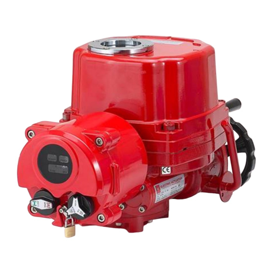
LCU-P
Installation, Operation & Maintenance Manual
Local Control Unit - P
(LCU-P with PCU function integrated)
Installation, Operation & Maintenance Manual
26, Emtibeui 28-ro, Siheung-si, Gyeonggi-do, (15119) Republic of Korea
Tel: +82-31-488-8266, Fax: 82-31-488-8269, www.hkcon.co.kr
Valve automation leader HKC
Doc. No.: HumG-LCUP-19 Rev.0 E
Page 1 / 14
Advertisement
Table of Contents

Related Manuals for HKC LCU-P

Summary of Contents for HKC LCU-P
- Page 1 LCU-P Installation, Operation & Maintenance Manual Local Control Unit - P (LCU-P with PCU function integrated) Installation, Operation & Maintenance Manual 26, Emtibeui 28-ro, Siheung-si, Gyeonggi-do, (15119) Republic of Korea Tel: +82-31-488-8266, Fax: 82-31-488-8269, www.hkcon.co.kr Valve automation leader HKC Doc. No.: HumG-LCUP-19 Rev.0 E...
-
Page 2: Table Of Contents
2. Check point before using the actuator ......................3 3. Standard Specification .............................. 4 4. Layout of LCU-P board ............................. 4 5. Main function and it’s usage for Local Control .................... 5 6. Main function and usage in Remote Manual Control ................6 Dry contacts control (command contact) ........................ -
Page 3: Introduction
1. Introduction Purpose The LCU-P unit was developed to add a PCU function to the LCU-B unit for the HQ and HL series electric actuators, and it is possible to add a communication module such as ProfiBus and ModBus for customer convenience. This manual is intended for safe use, installation and maintenance of the LCU-P. -
Page 4: Standard Specification
1500V ac, 1 minute Insulation resistance 500V dc, 50MΩ or more Vibration and shock Z axis 1g/3g, frequency: 100 – 200Hz, time: within 30 minutes 4. Layout of LCU-P board Front Back Valve automation leader HKC Doc. No.: HumG-LCUP-19 Rev.0 E... -
Page 5: Main Function And It's Usage For Local Control
When action is in opening progress, the open (red) LED is flickering. If Opening is completed, the open (red) LED will be maintaining as on. After that, the actuator is stopped. Valve automation leader HKC Doc. No.: HumG-LCUP-19 Rev.0 E Page 5 / 14... -
Page 6: Main Function And Usage In Remote Manual Control
Command function is activated when is input an action by external dry contact. 6.1.2 Hold / Inching can be selected by changing the 3-pin Dip Switch (SW2) specified in No. 20 of “4. LCU-P board layout”. ① Pin No.2 : select as Hold (On) / Inching (Off) 6.1.3... -
Page 7: External Output Signal Contacts
Checking with No.10 and No.13 terminal. The contact is changed when the actuator is fault (activated on the torque switch). It is possible to select the contact by 3-pin DIP switch (SW2) of LCU-P layout No20 as No1-On: B-contact, No1-Off: A-contact ④... -
Page 8: Main Function And Usage For Remote Modulating Control (Proportional Control)
Please make sure whether the input signal and DIP switches are correct as intended use. Caution : Zero switch SW3-3 is applied to input and output signals equally. Valve automation leader HKC Doc. No.: HumG-LCUP-19 Rev.0 E Page 8 / 14... -
Page 9: Set Feedback Type
This is called “Hunting” and the user must appropriately adjust the deadband to avoid from the hunting. 7.3.5 Continuous hunting causes a failure of the actuator parts such as motor, LCU-P board, potentiometer and etc. Deadtime setting Deadtime Module 7.4.1... -
Page 10: Auto Setting
Fail close (FC), fail open (FO) and fail stop When an analogue command signal does not come in or a wrong signal is received, the LCU-P will detect Fault and operates automatically open, close and stop according to specified fail position. -
Page 11: Auto Full Action (Af)
If there were not input anything for 2 minutes, the setting process is also cancelled. 7.10 Adjust output (feedback) signal 7.10.1 Proceed after select “Stop” of the mode knob for using this function. Valve automation leader HKC Doc. No.: HumG-LCUP-19 Rev.0 E Page 11 / 14... -
Page 12: Led Display
Analog or Auto Scan Flicker Close limit Close LED 3 Green Closing Flicker Torque trip Fault LED 4 Amber Malfunction Flicker Open limit Open LED 5 Opening Flicker Valve automation leader HKC Doc. No.: HumG-LCUP-19 Rev.0 E Page 12 / 14... -
Page 13: Error Display
Lose of set point Reverse turn the motor Abnormal of set point selection Abnormal of potentiometer Abnormal of opening Abnormal of closing 9. LCU-P operating Actuator position Fully close Fully open Input signal 4mA dc, 0V dc, 1V dc, 2V dc... -
Page 14: Lcu-P Wiring Diagram
LCU-P Installation, Operation & Maintenance Manual LCU-P wiring diagram HKC Co., Ltd. Address : 26, Emtibeui 28-ro, Siheung-si, Gyeonggi-do, (15119) Republic of Korea Tel: +82-31-488-8266, Fax: 82-31-488-8269, www.hkcon.co.kr Valve automation leader HKC Doc. No.: HumG-LCUP-19 Rev.0 E Page 14 / 14...
Need help?
Do you have a question about the LCU-P and is the answer not in the manual?
Questions and answers