
Summary of Contents for SurePoint SENTINEL
- Page 1 396-5477Y1 Installation Guide & Operator’s Manual 396-5477Y1 Sentinel Row Control Manual ©2022 SurePoint Ag Systems 4/29/2022...
- Page 2 396-5477Y1 Sentinel Row Control Manual ©2022 SurePoint Ag Systems 4/29/2022...
- Page 3 Setup & Operation • Getting Sentinel on VT ................... 30-31 • Sentinel Icons ....................32 • Sentinel Row Control & Row Monitoring Setup ........ 33-49 • • Setup Overview ..................... 34-35 • Settings - Product - Device Setup ..............36 •...
- Page 4 CAUTION: Indicates a potentially hazardous situation that, if not avoided, may result in minor or moderate injury. It may also be used to alert against unsafe practices. NOTICE is used to address safety practices not related to personal safety. 396-5477Y1 Sentinel Row Control Manual ©2022 SurePoint Ag Systems 4/29/2022...
- Page 5 A Word to the Operator It is YOUR responsibility to read and understand the safety messages in this manual. YOU are the key to safety. SAFETY IS YOUR RESPONSIBILITY. 396-5477Y1 Sentinel Row Control Manual ©2022 SurePoint Ag Systems 4/29/2022...
- Page 6 T3 Female x 3/4” HB 124-01-G11056-V Viton O-Ring for T1 fittings 124-01-G11058-V Viton O-Ring for T3 fittings 124-01-G11054-V Viton O-Ring for T4 fittings See next page for a list of T1 fittings 396-5477Y1 Sentinel Row Control Manual ©2022 SurePoint Ag Systems 4/29/2022...
- Page 7 Viton O-ring for T1 Fittings Sentinel Flow Meter Part Number Description 204-01-4625AAGB1B1 4-Row Sentinel flow meter 124-02-010001 T1 Fork 374-4024Y1 4-Pin Amp Superseal dust plug 384-1105 Hardware Kit - mounting bolts 396-5477Y1 Sentinel Row Control Manual ©2022 SurePoint Ag Systems 4/29/2022...
- Page 8 SurePoint Harness Layout for ISO Sentinel The SurePoint Sentinel module communicates with the Sentinel ECU through a proprie- tary communication network (CAN). The Sentinel ECU then, using the ISOBUS commu- Components nication protocol, relays the flow information through the tractor ISOBUS and generates the user interface on the in-cab display.
- Page 9 Sentinel Row Control Valve Interface 226-01-4211Y1 Communication When doing the Module Addressing pro- cess, first plug in all the Sentinel Flowmeter Add 4-pin modules, then go to Valve Module Diag- Extension where nostics and plug in all the Sentinel Row needed Control Valve Interface Modules.
- Page 10 Sentinel Row Control Valve Interface 226-01-4211Y1 CANBUS - Connect to Trunkline (CANBUS Device connector) dur- VALVE A -B -C -D ing Module addressing Connect to the correct process row control valve (match A - B - C - D with the Sentinel...
- Page 11 (400-3982Y1) to the toolbar, typically in the center of 4 rows if Step 4 possible, using provide u-bolts. 2. Mount the Sentinel Row Control Valve Interface to the Sentinel Row Control Valve Interface Mounting Bracket (400-4956Y1-BK) using the mounting hardware bag (384-1110 - Size 10 machine Step 5 screws, flat washers, and nylon lock nuts).
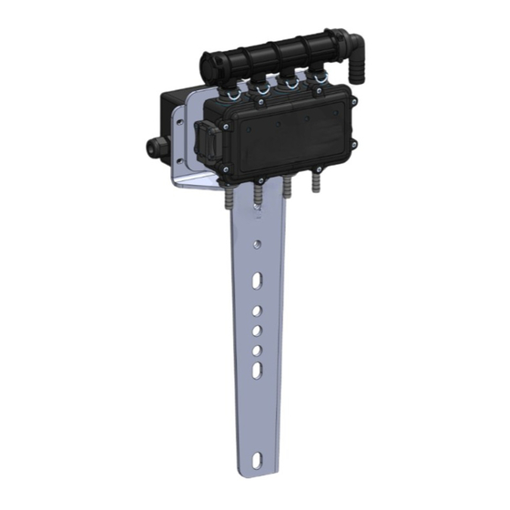
- Page 12 MODULE PLUMBING ASSEMBLY Flowmeter Module Plumbing Installation: 1. Mount the Sentinel Row Monitor flowmeter module to the mounting bracket using hardware kit (384-1105 - 5/16” hex head bolts and flange nuts). 2. Lubricate O-rings prior to installation in insert the inlet manifold (120-T3MT3F-4XT1M) into the top ports of the flowmeter module, flow direction is down.
- Page 13 4 rows if possible. 4. Route the 3/4” supply hose to the inlet port of the Sentinel Row Monitor Flowmeter Module manifold. 5. Route 3/8” OD tubing or 3/8” hose from the Sentinel Flowmeter Module to the Sentinel Row Control Valve located near the row unit.
- Page 14 CONFIGURATIONS 3/4” Hose Barb Tee (PumpRight PR17/PR30) or 1” x 3/4” Hose Barb Tee (PR40/D250) 527-16-100100 - 16 Row Sentinel Row Control Plumbing Kit 3/4” Hose Barb Tee (PumpRight PR17/PR30) or 1” x 3/4” Hose Barb Tee (PR40/D250) 527-24-100100 - 24 Row Sentinel Row Control Plumbing Kit 396-5477Y1 Sentinel Row Control Manual ©2022 SurePoint Ag Systems...
- Page 15 1” x 3/4” Hose Barb Tee (PR40/D250) 527-32-100100 - 32 Row Sentinel Row Control Plumbing Kit- PR17, PR30 Kit 527-32-100200 - 32 Row Sentinel Row Control Plumbing Kit- PR40, D250, PR80 Kit 3/4” Hose Barb Tee (PumpRight PR17/PR30) or 1” x 3/4” Hose Barb Tee (PR40/D250)
- Page 16 1. Mount the Sentinel Row Control valve and mounting bracket to the planter using one of the kit options below. 2. Route 3/8” OD tubing or 3/8” hose from the Sentinel Flowmeter Module to the row unit. Avoid pinch points on the planter and allow for row unit travel. Note: Lubricate 3/8”...
- Page 17 Flow Meter BUS 2 SHT 3/5C 4 PIN Deutsch Tower DT06-4S RD-18 208-06-2912Y1 Ignition WB-031 BK-14 SHT 4/4A GN-18 CAN Low YE-18 CAN High WB-045 RD-14 +12V DC SHT 4/5C 396-5477Y1 Sentinel Row Control Manual ©2022 SureFire Ag Systems 2/15/2022...
- Page 18 (Out 21) LSA P1 SHT 3/5B VT-18 RS232 TxD YE-18 WB-007 (ISOBUS) CAN2 High SHT 4/2B CAN4 High (In 12) Spare BL-18 WB-057 (In 8) P1 Flow SHT 5/5A (In 4) Right Speed 396-5477Y1 Sentinel Row Control Manual ©2022 SureFire Ag Systems 2/15/2022...
- Page 19 VT-WH-18 WB-073 (in 16) Pr Pressure 2 SHT 5/4C YE-18 WB-061 X-051 (Out 9) PWM1 I I mplement Switch SHT 5/2A WP Tower 2-pin 12015792 Signal WB-035 BK-18 SHT 4/4A 396-5477Y1 Sentinel Row Control Manual ©2022 SureFire Ag Systems 2/15/2022...
- Page 20 SHT 1/5C RD-14 WB-043 RD-14 BK-14 SP-005 WB-003 SHT 2/5A BK-14 SHT 1/2A BK-8 SP-003 SHT 1/2A 25.0 Amps BK-8 HC GND HC GND RD-8 SP-004 RD-8 HC PWR HC PWR 396-5477Y1 Sentinel Row Control Manual ©2022 SureFire Ag Systems 2/15/2022...
- Page 21 Section 8 WH-BL-18 WB-101 Section 9 WH-BK-18 Section 7 SHT 3/2B PK-18 WB-103 Section 10 WH-BR-18 Section 8 SHT 4/2A WH-YE-18 WB-105 Section 11 SHT 1/2C GN-18 WB-107 Section 12 396-5477Y1 Sentinel Row Control Manual ©2022 SureFire Ag Systems 2/15/2022...
- Page 22 WH-18 WB-119 Section 16 SHT 2/2B WH-GN-18 Section 17 GN-18 Section 18 WB-085 WH-GN-18 SP-024 WB-087 WH-GN-18 SHT 2/2C SHT 5/2B WB-089 GN-18 SP-025 WB-091 GN-18 SHT 3/2B SHT 5/3C 396-5477Y1 Sentinel Row Control Manual ©2022 SureFire Ag Systems 2/15/2022...
- Page 23 208-06-5022Y1 Connector pinouts for Rate Control and Row Control ISO Connector - 12-pin Flowmeter Bus 1 & 2 General Diagnostic Tips Valve A Valve B Gray OR-WH 396-5477Y1 Sentinel Row Control Manual ©2022 SureFire Ag Systems 2/15/2022...
- Page 24 4-Pin Deutsch CAN Trunklines to 4-Pin AMP SuperSeal to connect Sentinel Flowmeter Modules Number of Part # flowmeter Length connectors 208-06- 5’ 208-06-2909Y2 15’ 208-06-4975Y1 5’ 208-06-2910Y2 15’ CAN Device AMP SUPER SEAL TOWER 4-PIN 208-06-2911Y2 15’ 208-06-4976Y1 5’ +12VDC...
- Page 25 12 V Batt Power ISO CAN Lo Master Switch Connector 3 PIN DEUTSCH HD16-3-96S BLK 14 AWG ECU GND RED 14 AWG 12 V Batt Master Switch DUST CAP DEUTSCH HDC14-3-JDL 396-5477Y1 Sentinel Row Control Manual ©2022 SureFire Ag Systems 2/15/2022...
- Page 26 1. Mount pump in your preferred location. The PumpRight pump has excellent suction and priming ability, so it can be mounted away from or above fertilizer tanks. 2. SurePoint has U-Bolts available to mount the pump directly to multiple bar sizes shown below. Each U- bolt kit includes 1 bolt and 2 flange nuts.
- Page 27 If the load sense is needed, do this: First, remove the load sense plug and install a #6 male boss x #6 JIC adapter fitting, SurePoint PN 161-01-6MB-6MJ. Then run a 3/8” or 1/4”...
- Page 28 PumpRight after the seed distribution fan. If using this method, the SurePoint PWM bypass valve must be open (see previous page for instruction & picture). If bypass is left closed, the SurePoint valve will limit the speed of the seed distribution fan.
- Page 29 PumpRight Hydraulic Oil Flow Requirements (Requirements for 4.0 CID Motor—standard SurePoint motor beginning in 2016— Earlier motor was 4.9 CID which uses 20% more oil) Setting Tractor Hydraulic Remote Speed PumpRight pumps require a constant hydraulic oil flow from Model PR17 - 3 Diaphragms the tractor.
- Page 30 Pressure Relief Valve (PRV) is installed and functioning so system pressure will be kept under 100 PSI. Check hoses, hose clamps, and liquid fittings regularly and repair or replace loose connections. 396-5477Y1 Sentinel Row Control Manual ©2022 SurePoint Ag Systems 4/29/2022...
- Page 31 (290 PSI). Be sure the 100 PSI Pressure Relief Valve (PRV) is installed and functioning so system pressure will be kept under 100 PSI. Check hoses, hose clamps, and liquid fittings regularly and repair or replace loose connections. 396-5477Y1 Sentinel Row Control Manual ©2022 SurePoint Ag Systems 4/29/2022...
- Page 32 How to get to Sentinel on the VT (or UT) John Deere 2630 Display Pro 700 Display You can set up VT Upload and VT Implements on Toolbox > Layout (shown in Left Area above). On first bootup, VT Up- load may take several minutes for a new device.
- Page 33 How to get to Sentinel on the VT (or UT) Ag Leader InCommand Trimble TMX-2050 396-5477Y1 Sentinel Row Control Manual ©2022 SurePoint Ag Systems 4/29/2022...
- Page 34 IMPLEMENT Setup -enter imple- Next VT - when more than one display ment geometry is in use, this moves the Sentinel to the next screen. (v.1.3.0) Save to this VT - when more than one SPEED Setup - select speed source display is available.
- Page 35 Sentinel Row Control and Flow Monitoring ECU Harness- 2 products - 18 sections 208-06-4099Y4 Sentinel Row Control and Flow Monitoring ECU Harness - 2 products - 18 sections 208-06-4984Y2 Sentinel Row Control and Flow Monitoring ECU Harness - 4 products - 18 sections...
- Page 36 Set-up and Configuration for Row Control & Row Monitoring The following pages will guide you through the initial set-up and configuration of your Sentinel Row Control & Row Monitoring system. Below is an overview of the steps necessary to fully configure the system before operation.
- Page 37 Sentinel Setup and Configuration The following pages will guide you through the initial set-up and configuration of your Sentinel Row Control & Row Monitoring system. Below is an overview of the steps necessary to fully configure the system before operation. Each subsequent page outlines the page features as well as the sequence of buttons used to navigate to that page from the HOME screen.
- Page 38 4.) Enter a name for the Product. 5.) Press the box under “Device”. 6.) Select “Liquid Row Control + Monitor” for Row Control and to use the Sentinel flowmeter modules for row flow monitoring. (If Liquid Row Control + Monitor is not an option, call SurePoint to get an unlock code (no charge).)
- Page 39 19.) Control Integral (Ki) - Tech Support use 20.) Interplant Mode - 21.) Module Orientation - ABCD if Row 1 is A. DCBA if Row 1 is D on the Sentinel flowmeter module. 22.) Press the Back Arrow when finished with this screen.
- Page 40 28.) Use Master Switch - check this box if a Master Switch (Foot Switch) is to be used by Sentinel. 29.) Use Height Switch - Check this if the Sentinel has a dedicated height switch. 30.) Setup : Choose switch or sensor.
- Page 41 Normal ranges for both are 5% to 15%. SETUP for 2 products with Row Control and Row Flow Monitoring If you are setting up Sentinel to do row control Product 2 will usually start with the next row after...
- Page 42 Sentinel Setup and Configuration Addressing Sentinel Flow Modules & Valve Control Module Interface Module Diagnostics Screen Flow Module & Valve Module Diagnostics To address the Sentinel flow modules, start by having all the modules plugged in. From this screen, push Reset All Addresses.
- Page 43 This may be necessary after a software update or feature unlock or if some screens or features do not appear correct. 44.) Next VT - press to push Sentinel to another virtual terminal. This may be necessary if there is more than one monitor or display in the cab.
- Page 44 PWM % to set the pump speed for agitation (usually 30-40%) 2.) DIAGNOSTIC TAB - Observe the system param- eters during operation. 3.) SurePoint - press for version information 4.) Press starburst for Auxiliary Settings Screen and to enter Unlock Code. Do not use this screen without authorization.
- Page 45 7.) Flow Adj for this row only. Normally 1.00. 8.) Row Control Module information that may be helpful for SurePoint tech support. 9.) Press the SurePoint button to go to the Software Version and Auxiliary Settings screens. 396-5477Y1 Sentinel Row Control Manual ©2022 SurePoint Ag Systems...
- Page 46 SurePoint. Contact Sure- Point and provide the ECU Serial # to get the un- lock code. 9.) Enter the unlock code obtained from SurePoint. Sentinel Feature Unlocker (SurePoint Tech Support Only) 396-5477Y1 Sentinel Row Control Manual ©2022 SurePoint Ag Systems...
- Page 47 Customizable Toolbar & Totalizer Counters - Acres - Hours - Gallons Sentinel has 3 totalizer counters to keep track of acres, hours, and gallons. Any of these may be set up on the Customizable Toolbar near the top of the Product Run Screen. If these are not on the Customizable Toolbar, the values may still be seen by pressing the Reset Totals button on the Rate Setup screen.
- Page 48 Sentinel Row Control & Row Monitoring Operation 1.) When operating with RATE CONTROL and ROW FLOW MONITORING, the Wheat but- ton in the top right corner gives you the top half of the screens below. Row Bar View Row Bar Button 2.) Pressing the Row Bar Button in the lower left corner gives you the Row Bar View on the bottom half of...
- Page 49 Sentinel Row Control Operation Once the Sentinel has been set up in the display, little is required of the user to operate the Sentinel. The system can be started with an Implement Switch that will turn the system on when the implement is lowered.
- Page 50 Sentinel HOME Screen for Row Control -- Setup and Diagnostic Tabs Setup values are shown for electric pump system (usually Setup values are shown for typical PR hydraulic pump not used on Row Control systems). These can be adjusted system. These can be adjusted as necessary for best op- as necessary for best operation.
- Page 51 When testing with water, the pressure will be less than it will be with a heavier, thicker fertilizer. Increase the speed or rate to increase the pressure. 396-5477Y1 Sentinel Row Control Manual ©2022 SurePoint Ag Systems 4/29/2022...
- Page 52 1. Is MASTER ON? Is there a SPEED? Is there a RATE? Switch Section Control from AUTO to MANUAL. 2. On Hardware screen, uncheck TASK CONTROL. If you have TASK CONTROL checked on the Sentinel, Task Control must be activated and turned ON on the display software.
- Page 53 Hydraulic Pump Will Not Turn Turn hydraulics off, go to the SurePoint Hydraulic PWM valve and use the manual override (red knob) on top of the electric coil to manually open the valve (Manual Override UP = valve fully open). There may be dirt in here that needs to be cleaned out before you can turn and raise the override.
- Page 54 When addressing, module 2 will display as “not expected.” When plugged in, it will be issued an address and 6 rows will display on the Sentinel HOME screen. The last 2 rows on the module will be ignored.
- Page 55 Sentinel Row Flow Troubleshooting Sentinel alarms too often Often times during initial start-up the Sentinel alarms can seem excessive as Sentinel highlights the row-to- row inaccuracies in the system. Small things like tubing lengths and check valve springs can make big differ- ences in row-flow.
- Page 56 Maintenance Cleaning Under no circumstance should the Sentinel modules or ECU be cleaned with a pressure washer. While the flow modules and ECU are sealed, the intense pressure generated by pressure washers may penetrate the seals and cause irreversible damage.
- Page 57 PSI). Be sure the 100 PSI Pressure Relief Valve (PRV) is installed and functioning so system pressure will be kept under 100 PSI. Check hoses, hose clamps, and liquid fit- tings regularly and repair or replace loose connections. 396-5477Y1 Sentinel Row Control Manual ©2022 SurePoint Ag Systems 4/29/2022...
- Page 58 PR80 Pump Service Kit - 4 Diaphragm KIT #: 291-13-100250 (pump requires 4 kits) 291-13-304083 BlueFlex Diaphragm 291-13-3049050 Valve 291-13-3040200 Gasket / O-Ring Visit www.SurePointag.com or www.support.SurePointag.com for PumpRight Diaphragm Pump Repair and Maintenance Video 396-5477Y1 Sentinel Row Control Manual ©2022 SurePoint Ag Systems 4/29/2022...
- Page 59 See Note Below Pump Head Wobble Plate/Diaphragm BlueFlex Sleeve Keeper Washer Inlet Valve NOTE: A multipurpose grease is fine to use for applying in between the Diaphragm and Wobble Plate/Washer 396-5477Y1 Sentinel Row Control Manual ©2022 SurePoint Ag Systems 4/29/2022...
- Page 60 Breakout Diagrams in 396-4034Y1, the PumpRight manual that came with your pump. Also see the manual and individual pump parts breakouts online here. (store.SurePointag.com) Go to support.SurePointag.com for pump information and parts breakdowns. 396-5477Y1 Sentinel Row Control Manual ©2022 SurePoint Ag Systems 4/29/2022...
- Page 61 PWM Valve and Motor Parts 164-FTA0994 4.0 CID motor (this is the standard motor beginning in 2016) Maintenance 164-FTA1609 Same as 164-FTA0994, but with RPM Speed Sensor-- ©2012-2022 SurePoint Ag Systems—All Rights Reserved 396-5477Y1 Sentinel Row Control Manual ©2022 SurePoint Ag Systems 4/29/2022...
Need help?
Do you have a question about the SENTINEL and is the answer not in the manual?
Questions and answers