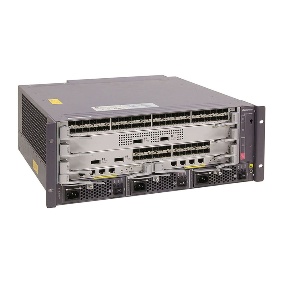
Huawei Quidway S9300 Hardware Description
Terabit routing switch
Hide thumbs
Also See for Quidway S9300:
- Configuration manual - network management (630 pages) ,
- Configuration manual (603 pages) ,
- Configuration manual - multicast (262 pages)

Related Manuals for Huawei Quidway S9300


Summary of Contents for Huawei Quidway S9300
- Page 1 Quidway S9300 Terabit Routing Switch V100R003C01 Hardware Description Issue Date 2010-12-15 HUAWEI TECHNOLOGIES CO., LTD.
- Page 3 All other trademarks and trade names mentioned in this document are the property of their respective holders. Notice The purchased products, services and features are stipulated by the contract made between Huawei and the customer. All or part of the products, services and features described in this document may not be within the purchase scope or the usage scope.
-
Page 5: About This Document
Quidway S9300 Terabit Routing Switch Hardware Description About This Document About This Document Intended Audience This document provides an overall description of the S9300, details about each chassis and board, cables available to the device, and lists of components. This document describes hardware features of the S9300, which helps intended readers obtain detailed information about each chassis, board, and cable, and rapidly locate specific information through lists of components. - Page 6 Quidway S9300 Terabit Routing Switch About This Document Hardware Description Change History Updates between document issues are cumulative. Therefore, the latest document issue contains all updates made in previous issues. Changes in Issue 01 (2010-12-15) Initial commercial release. Huawei Proprietary and Confidential Issue 01 (2010-12-15) Copyright ©...
-
Page 7: Table Of Contents
Quidway S9300 Terabit Routing Switch Hardware Description Contents Contents About This Document........................iii 1 Cabinets............................1-1 1.1 Introduction to the N66E Cabinet........................1-2 1.1.1 Appearance of the N66E Cabinet......................1-2 1.1.2 Technical Specifications of the N66E Cabinet..................1-3 1.1.3 Components of the N66E Cabinet......................1-4 1.1.4 Operating Environment of the N66E Cabinet..................1-5 1.1.5 Structural Features of the N66E Cabinet....................1-5... - Page 8 Quidway S9300 Terabit Routing Switch Contents Hardware Description 3.3 AC Power Supply............................3-11 3.3.1 Appearance............................3-11 3.3.2 Panel..............................3-11 3.3.3 Function Overview..........................3-13 3.3.4 Technical Specifications........................3-13 4 Heat Dissipation System......................4-1 4.1 Introduction..............................4-2 4.1.1 Heat Dissipation System of the S9312....................4-2 4.1.2 Heat Dissipation System of the S9306....................4-2 4.1.3 Heat Dissipation System of the S9303....................4-3...
- Page 9 Quidway S9300 Terabit Routing Switch Hardware Description Contents 5.4.2 Function and Application........................5-25 5.4.3 Panel..............................5-25 5.4.4 Technical Specifications........................5-26 5.5 VSTSA - Stacking Card on the Main Control Board..................5-26 5.5.1 Introduction............................5-26 5.5.2 Function and Application........................5-26 5.5.3 Panel..............................5-27 5.5.4 Interfaces..............................5-28 5.5.5 Technical Specifications........................5-29 5.6 CMU - Centralized Monitoring Unit......................5-29...
- Page 10 Quidway S9300 Terabit Routing Switch Contents Hardware Description 5.10.5 Interface Attributes..........................5-46 5.10.6 Technical Specifications........................5-47 5.11 G48CEAT - 12-Port 100M/1000M Ethernet Optical Interface + 36-Port 100M/1000M Combo LPU (EA, RJ45/SFP)................................5-47 5.11.1 Introduction............................5-47 5.11.2 Function and Application........................5-48 5.11.3 Panel..............................5-48 5.11.4 Interfaces............................5-49 5.11.5 Interface Attributes..........................5-49 5.11.6 Technical Specifications........................5-52...
- Page 11 Quidway S9300 Terabit Routing Switch Hardware Description Contents 5.16.3 Panel..............................5-70 5.16.4 Interfaces............................5-71 5.16.5 Interface Attributes..........................5-71 5.16.6 Technical Specifications........................5-74 5.17 T24XA - 24-Port 100M/1000M Ethernet Electrical and 2-Port 10GE Optical Interface Card (EA, SFP/XFP) .....................................5-75 5.17.1 Introduction............................5-75 5.17.2 Function and Application........................5-75 5.17.3 Panel..............................5-75...
- Page 12 Quidway S9300 Terabit Routing Switch Contents Hardware Description 5.22.2 Function and Application........................5-96 5.22.3 Panel..............................5-96 5.22.4 Interfaces............................5-97 5.22.5 Interface Attributes..........................5-97 5.22.6 Technical Specifications........................5-98 5.23 CKM - Clock Board............................5-99 5.23.1 Introduction............................5-99 5.23.2 Function and Application........................5-99 5.23.3 Interfaces............................5-100 5.23.4 Interface Attributes...........................5-100 5.23.5 Technical Specifications........................5-101 6 Cables............................6-1...
- Page 13 Quidway S9300 Terabit Routing Switch Hardware Description Contents 6.8.2 Structure...............................6-17 6.8.3 Technical Specifications........................6-17 7 List of Indicators.........................7-1 7.1 Fan Module Indicators............................ 7-2 7.2 Power Supply Indicators..........................7-2 7.3 SRU Indicators..............................7-3 7.4 MCUA Indicators............................7-4 7.5 LPU Indicators..............................7-5 7.6 CMU Indicators...............................7-6 8 List of Boards..........................8-1...
- Page 15 Quidway S9300 Terabit Routing Switch Hardware Description Figures Figures Figure 1-1 N66E cabinet............................1-3 Figure 1-2 Components of the rear-serviceable N66E cabinet................1-4 Figure 1-3 Cable apertures on the cabinet top......................1-6 Figure 1-4 ESD jack on the N66E cabinet......................1-7 Figure 1-5 Combined N66E cabinets........................1-7 Figure 1-6 Appearance of the N68E cabinet......................1-9...
- Page 16 Quidway S9300 Terabit Routing Switch Figures Hardware Description Figure 4-6 S9312 heat dissipation zones......................4-6 Figure 4-7 Air filter of the S9312.........................4-7 Figure 4-8 Air filter of the S9306.........................4-7 Figure 4-9 Air filter of the S9303.........................4-8 Figure 5-1 Slots of the S9312..........................5-7 Figure 5-2 Slots of the S9306..........................5-7...
- Page 17 Quidway S9300 Terabit Routing Switch Hardware Description Figures Figure 6-5 Appearance of the LC/PC optical connector..................6-12 Figure 6-6 Clock cable connections........................6-13 Figure 6-7 Structure of the 120Ω trunk cable.....................6-14 Figure 6-8 Structure of the straight-through cable.....................6-14 Figure 6-9 SMB/SMB trunk cable........................6-15 Figure 6-10 SMB/BNC trunk cable........................6-15...
- Page 19 Quidway S9300 Terabit Routing Switch Hardware Description Tables Tables Table 1-1 Technical specifications of the N66 cabinet..................1-3 Table 1-2 Requirements for the operating environment of the N66E cabinet............1-5 Table 1-3 Technical specifications of the N68E cabinet..................1-9 Table 1-4 Requirements for the operating environment of the N68E cabinet............1-11 Table 2-1 Components of the S9312........................2-5...
- Page 20 Quidway S9300 Terabit Routing Switch Tables Hardware Description Table 5-16 Attributes of the 10M/100M Base-TX Ethernet interface...............5-22 Table 5-17 Attributes of the console interface....................5-22 Table 5-18 Attributes of the RS485 interface.....................5-23 Table 5-19 Attributes of the MON interface......................5-23 Table 5-20 Attributes of the BITS interfaces.....................5-23 Table 5-21 Technical specifications of the MCUA....................5-24...
- Page 21 Quidway S9300 Terabit Routing Switch Hardware Description Tables Table 5-58 Attributes of the 100M/1000M Base-T Ethernet electrical interface..........5-52 Table 5-59 Technical specifications of the G48CEAT..................5-52 Table 5-60 Lists of F48S............................5-53 Table 5-61 Description of buttons and indicators on the F48S panel..............5-54 Table 5-62 Types and functions of the interfaces on the F48S................5-54...
- Page 22 Quidway S9300 Terabit Routing Switch Tables Hardware Description Table 5-100 Description of buttons and indicators on the G24S panel..............5-80 Table 5-101 Types and functions of the interfaces on the G24S................5-81 Table 5-102 Attributes of the 1000M Base-SFP Ethernet optical interfaces.............5-81 Table 5-103 Attributes of the SFP optical module (1000 Mbit/s)..............5-82...
- Page 23 Quidway S9300 Terabit Routing Switch Hardware Description Tables Table 6-9 Pin assignments of the crossover cable....................6-10 Table 6-10 Technical specifications of the straight-through cable..............6-10 Table 6-11 Technical specifications of the crossover cable................6-11 Table 6-12 Types of the optical fibers........................6-11 Table 6-13 Technical specifications of the optical fiber..................6-12 Table 6-14 Technical specifications of the stack cables..................6-17...
-
Page 25: Cabinets
Quidway S9300 Terabit Routing Switch Hardware Description 1 Cabinets Cabinets About This Chapter This chapter describes the N66E and N68E cabinets. NOTE l S9300The N68E and N66E cabinets are standard configurations. The cabinets facilitate maintenance and capacity expansion. In addition, two switches can be located in a cabinet side by side. -
Page 26: Introduction To The N66E Cabinet
Quidway S9300 Terabit Routing Switch 1 Cabinets Hardware Description 1.1 Introduction to the N66E Cabinet This topic describes the appearance, technical specifications, components, operating environment, and structural features of the N66E cabinet. 1.1.1 Appearance of the N66E Cabinet This topic describes the appearance of the N66E cabinet. Being compliant with the IEC 60297-2 standard, the N66E cabinet is designed with a modular structure, which facilitates expansion and maintenance. -
Page 27: Technical Specifications Of The N66E Cabinet
Quidway S9300 Terabit Routing Switch Hardware Description 1 Cabinets Figure 1-1 N66E cabinet 1.1.2 Technical Specifications of the N66E Cabinet This topic describes the technical specifications of the N66E cabinet, including the maximum installation height inside the cabinet, dimensions, and weight of an empty cabinet. -
Page 28: Components Of The N66E Cabinet
Quidway S9300 Terabit Routing Switch 1 Cabinets Hardware Description NOTE l 1 U = 1.75 in. or 44.45 mm. and U is the height unit defined in the IEC 60297 standard. l The weight of an empty cabinet consists of the weight of the front door, rear door, and side panels. -
Page 29: Operating Environment Of The N66E Cabinet
Quidway S9300 Terabit Routing Switch Hardware Description 1 Cabinets 1.1.4 Operating Environment of the N66E Cabinet This topic describes the ambient temperature and relative humidity in the operating environment of the N66E cabinet. To ensure long-term reliability of the equipment, the equipment room must have a stable temperature and humidity. -
Page 30: Figure 1-3 Cable Apertures On The Cabinet Top
Quidway S9300 Terabit Routing Switch 1 Cabinets Hardware Description Figure 1-3 Cable apertures on the cabinet top 52mm 52mm Network Network cable/fiber cable/fiber 175mm×22mm Reserved holes 500mm 500mm Power cable hole Power cable Front Door Heat Dissipation The front door, rear door, and top plate of the N66E cabinet have high-density air vents. -
Page 31: Figure 1-4 Esd Jack On The N66E Cabinet
Quidway S9300 Terabit Routing Switch Hardware Description 1 Cabinets Figure 1-4 ESD jack on the N66E cabinet Installation Scenarios The installation scenarios of the N66E cabinet are as follows: The cabinet can be installed on the concrete floor. The cabinet can also be installed on the antistatic floor. In this case, the N6X series supports are required. -
Page 32: Introduction To The N68E Cabinet
Quidway S9300 Terabit Routing Switch 1 Cabinets Hardware Description 1.2 Introduction to the N68E Cabinet This section describes the appearance, technical specifications, components, and structural features of the N68E cabinet. 1.2.1 Appearance of the N68E cabinet The N68E cabinet complies with the requirement of the Dimensions of Mechanical Structures of the 482.6 mm (19 Inch) Series (IEC 60297-2 Standard). -
Page 33: Technical Specifications Of The N68E Cabinet
Quidway S9300 Terabit Routing Switch Hardware Description 1 Cabinets Figure 1-6 Appearance of the N68E cabinet 1.2.2 Technical Specifications of the N68E cabinet The technical specifications of the N68E cabinet consist of the maximum installation height inside the cabinet, dimensions, and weight of an empty cabinet. -
Page 34: Components Of The N68E Cabinet
Quidway S9300 Terabit Routing Switch 1 Cabinets Hardware Description NOTE l 1 U = 1.75 in. or 44.45 mm. U is the height unit defined in the IEC 60297 standard. l The weight of an empty cabinet includes the weight of the front door, rear door, left side panel, and right side panel. -
Page 35: Structural Features Of The N68E Cabinet
Quidway S9300 Terabit Routing Switch Hardware Description 1 Cabinets Table 1-4 Requirements for the operating environment of the N68E cabinet Ambient Temperature Relative Humidity l Long term: 5°C to 40°C l Long term: 5% to 85% RH l Short term: -5°C to +45°C... -
Page 36: Figure 1-8 Cable Apertures On The Cabinet Top
Quidway S9300 Terabit Routing Switch 1 Cabinets Hardware Description Figure 1-8 Cable apertures on the cabinet top 52mm 52mm Network Network cable/fiber cable/fiber 312mm 312mm 130mm×15mm 130mm×15mm 312mm 312mm 145mm×65mm 145mm×65mm Reserved holes Power cable Front Door ESD Jack Before installing the N68E cabinet, you must wear an ESD-preventive wrist strap and ensure... -
Page 37: Figure 1-10 Combined N68E Cabinets
Quidway S9300 Terabit Routing Switch Hardware Description 1 Cabinets Heat Dissipation The front door, rear door, and bottom plate of the N68E cabinet have high-density air vents. Therefore, the N68E cabinet supports front air intake, back air exhaust, and upper air exhaust and provides good heat dissipation performance. - Page 38 Quidway S9300 Terabit Routing Switch 1 Cabinets Hardware Description 1-14 Huawei Proprietary and Confidential Issue 01 (2010-12-15) Copyright © Huawei Technologies Co., Ltd.
-
Page 39: Overview Of The S9300
Quidway S9300 Terabit Routing Switch Hardware Description 2 Overview of the S9300 Overview of the S9300 About This Chapter This chapter describes the characteristics, structure, system parameters, and physical specifications of the S9300. 2.1 Introduction This section describes the characteristics of the S9300. -
Page 40: Introduction
Quidway S9300 Terabit Routing Switch 2 Overview of the S9300 Hardware Description 2.1 Introduction This section describes the characteristics of the S9300. Position The S9300 is a high end Ethernet switch with large capacity and high performance. It mainly functions as an access node or aggregation node on the metropolitan area network (MAN) or a core switch on an enterprise network, providing Fast Ethernet (FE), Gigabit Ethernet (GE), and 10GE interfaces. -
Page 41: S9312
Quidway S9300 Terabit Routing Switch Hardware Description 2 Overview of the S9300 2.2.1 S9312 2.2.2 S9306 2.2.3 S9303 2.2.1 S9312 The S9312 is 15 U (1 U = 44.45 mm) high, with dimensions of 442 mm x 476 mm x 663.95 mm (width x depth x height). -
Page 42: Figure 2-2 Appearance And Components Of The S9312 (2)
Quidway S9300 Terabit Routing Switch 2 Overview of the S9300 Hardware Description Figure 2-2 Appearance and components of the S9312 (2) 1. Air filter 2. Fan Huawei Proprietary and Confidential Issue 01 (2010-12-15) Copyright © Huawei Technologies Co., Ltd. -
Page 43: Figure 2-3 Layout Of Slots On The S9312
Quidway S9300 Terabit Routing Switch Hardware Description 2 Overview of the S9300 Figure 2-3 Layout of slots on the S9312 SLOT12-LPU SLOT11-LPU SLOT10-LPU SLOT9-LPU SLOT8-LPU SLOT7-LPU SLOT14-SRU SLOT13-SRU SLOT6-LPU SLOT5-LPU SLOT4-LPU SLOT3-LPU SLOT2-LPU SLOT1-LPU The S9312 uses an integrated chassis of which the main components are described in Table 2-1. -
Page 44: S9306
Quidway S9300 Terabit Routing Switch 2 Overview of the S9300 Hardware Description Component Description Reference Fan module The fan modules are installed at the rear of the 4.2 Fan equipment. The equipment must be equipped with Module. four fan modules. -
Page 45: Figure 2-5 Appearance And Components Of The S9306 (2)
Quidway S9300 Terabit Routing Switch Hardware Description 2 Overview of the S9300 Figure 2-5 Appearance and components of the S9306 (2) 1. Air filter 2. Fan Figure 2-6 Layout of slots on the S9306 SLOT6-LPU SLOT5-LPU SLOT4-LPU SLOT8-SRU SLOT7-SRU SLOT3-LPU... -
Page 46: S9303
Quidway S9300 Terabit Routing Switch 2 Overview of the S9300 Hardware Description Table 2-2 Components of the S9306 Component Description Reference The SRUs are installed in slot 7 and slot 8 and 5.2 SRU - Main work in 1:1 backup mode with the data switching Control Unit. -
Page 47: Figure 2-8 Appearance And Components Of The S9303 (2)
Quidway S9300 Terabit Routing Switch Hardware Description 2 Overview of the S9300 4. LPU 5. PoE Power Module 6. Cabling rack Figure 2-8 Appearance and components of the S9303 (2) 1. Fan 2. Air filter Figure 2-9 Layout of slots on the S9303... -
Page 48: System Configuration And Physical Specifications
Quidway S9300 Terabit Routing Switch 2 Overview of the S9300 Hardware Description Component Description Reference Power supply The power supplies are installed in slots PWR1 3 Power and PWR2. The S9303 can use DC or AC power Supply. supplies. Cabling rack The cable distribution posts are located on the right side of the board cage of the S9303. - Page 49 Quidway S9300 Terabit Routing Switch Hardware Description 2 Overview of the S9300 Item Configuratio Configuratio Configuratio Note n of the S9312 n of the S9306 n of the S9303 FE/GE port density Forwarding 1320 Mpps 1080 Mpps 540 Mpps capability...
-
Page 50: Physical Specifications
Quidway S9300 Terabit Routing Switch 2 Overview of the S9300 Hardware Description rate of each GE interface is 1 Gbit/s; therefore, the interface capacity of the S9312 is 576 Gbit/s. 2.3.2 Physical Specifications Physical Specifications of S9312 Table 2-5 shows the physical specifications of the S9312. -
Page 51: Table 2-6 Physical Specifications Of The S9306
Quidway S9300 Terabit Routing Switch Hardware Description 2 Overview of the S9300 Physical Specifications of S9306 Table 2-6 shows the physical specifications of the S9306. Table 2-6 Physical specifications of the S9306 Item Specification Dimensions (width x depth x height, 442 mm x 476 mm x 441.7 mm (10 U high) - Page 52 Quidway S9300 Terabit Routing Switch 2 Overview of the S9300 Hardware Description Item Specification Maximum power 350 W (full configuration) Noise at normal temperature 58.6 db Weight Full configuration 22 kg DC input Rated voltage -48V/-60 V DC Allowed voltage -48 V:- 38.4 V to -57.6 V DC...
-
Page 53: Power Supply
Quidway S9300 Terabit Routing Switch Hardware Description 3 Power Supply Power Supply About This Chapter This chapter describes the AC power supply and DC power supply of the S9300. 3.1 Introduction This section provides an overview of the AC power supply and DC power supply of the S9300. -
Page 54: Introduction
Quidway S9300 Terabit Routing Switch 3 Power Supply Hardware Description 3.1 Introduction This section provides an overview of the AC power supply and DC power supply of the S9300. CAUTION l Do not install DC power supply and AC power supply on the same S9300. -
Page 55: Figure 3-1 Configuration Of The S9312 Power Supplies
Quidway S9300 Terabit Routing Switch Hardware Description 3 Power Supply Figure 3-1 Configuration of the S9312 power supplies AreaA Area B You can use DC power supplies or AC power supplies on the S9312. DC power supplies, 1+1 configuration Each power supply is configured in active area A and standby area B. The two power... - Page 56 Quidway S9300 Terabit Routing Switch 3 Power Supply Hardware Description The S9312 can use two AC power supplies in 1+1 configuration or four AC power supplies in 2+2 configuration. You can select the 1+1 configuration or 2+2 configuration according to the power supply requirements of the system.
-
Page 57: Figure 3-2 Configuration Of The S9306 Power Supplies
Quidway S9300 Terabit Routing Switch Hardware Description 3 Power Supply Figure 3-2 Configuration of the S9306 power supplies AreaA AreaB You can use DC power supplies or AC power supplies on the S9306. DC power supplies, 1+1 configuration Each power supply is configured in active area A and standby area B. The two power... -
Page 58: Power Supply Principle
Quidway S9300 Terabit Routing Switch 3 Power Supply Hardware Description – Each AC power supply is configured in PWR2 and PWR4, and the filler panels are installed in PWR1 and PWR3. – Each AC power supply is configured in PWR1 and PWR4, and the filler panels are installed in PWR2 and PWR3. -
Page 59: Figure 3-4 Principle Of The Dc Power Supplies On The S9300
Quidway S9300 Terabit Routing Switch Hardware Description 3 Power Supply Figure 3-4 Principle of the DC power supplies on the S9300 Board 2 Board n Board 1 Backplane RTN1 RTN2 -48V1/-60V1 -48V2/-60V2 PWR1 PWR2 -48/-60V -48/-60V -48V1/-60V1 -48V2/-60V2 RTN1 RTN2... -
Page 60: Dc Power Supply
Quidway S9300 Terabit Routing Switch 3 Power Supply Hardware Description Figure 3-5 Principle of the AC power supplies on the S9300 Board n Board 1 Board 2 Backplane -48VA -48VA -48VB -48VB RTNA RTNA RTNB RTNB PWR1 PWR2 PWR3 PWR4... -
Page 61: Panel
Quidway S9300 Terabit Routing Switch Hardware Description 3 Power Supply Figure 3-6 Appearance of the DC power supply of the S9300 3.2.2 Panel Figure 3-7 shows the panel of the DC power supply. Figure 3-7 Panel and components of the DC power supply of the S9300... -
Page 62: Function Overview
Quidway S9300 Terabit Routing Switch 3 Power Supply Hardware Description Indicator Color Description INPUT Green If the indicator is on, it indicates that the -48 V power input is normal. If the indicator is off, it indicates that the -48 V power input is unavailable. -
Page 63: Ac Power Supply
Quidway S9300 Terabit Routing Switch Hardware Description 3 Power Supply 3.3 AC Power Supply This section describes the appearance, panel, functions, and technical specifications of the AC power supply on the S9300. 3.3.1 Appearance 3.3.2 Panel 3.3.3 Function Overview 3.3.4 Technical Specifications 3.3.1 Appearance... -
Page 64: Figure 3-9 Panel Of The Ac Power Supply
Quidway S9300 Terabit Routing Switch 3 Power Supply Hardware Description Figure 3-9 Panel of the AC power supply FAULT 1. Power input 2. Handle 3. Switch 4. Indicator Table 3-4 describes the indicators of the AC power supply. Table 3-4 Description of the indicators of the AC power supply... -
Page 65: Function Overview
Quidway S9300 Terabit Routing Switch Hardware Description 3 Power Supply 3.3.3 Function Overview The 220V AC power supply provides 800W power and the 110V power supply provides 400W power. In addition, the AC power supply supports EMC filtering and provides the following... -
Page 67: Heat Dissipation System
Quidway S9300 Terabit Routing Switch Hardware Description 4 Heat Dissipation System Heat Dissipation System About This Chapter This chapter describes the heat dissipation system of the S9300, including fans and air filters. 4.1 Introduction This section provides an overview of the heat dissipation system of the S9300. -
Page 68: Introduction
Quidway S9300 Terabit Routing Switch 4 Heat Dissipation System Hardware Description 4.1 Introduction This section provides an overview of the heat dissipation system of the S9300. 4.1.1 Heat Dissipation System of the S9312 4.1.2 Heat Dissipation System of the S9306 4.1.3 Heat Dissipation System of the S9303... -
Page 69: Heat Dissipation System Of The S9303
Quidway S9300 Terabit Routing Switch Hardware Description 4 Heat Dissipation System Figure 4-2 Airflow in the S9306 4.1.3 Heat Dissipation System of the S9303 The heat dissipation system ensures that the S9303 operates in the normal temperature. For the temperature requirements, see 2.3.2 Physical... -
Page 70: Constitution Of The Fan Module
Quidway S9300 Terabit Routing Switch 4 Heat Dissipation System Hardware Description The heat dissipation system of the S9300 is divided into several zones and fan speed can be dynamically adjusted. 4.2.1 Constitution of the Fan Module The S9300 uses the modularized fans. The S9303, S9306, and S9312 use the same type of fans. -
Page 71: Fan Module Functions
Quidway S9300 Terabit Routing Switch Hardware Description 4 Heat Dissipation System 4.2.3 Fan Module Functions The heat dissipation system of the S9300 is divided into several zones and fan speed can be dynamically adjusted. CAUTION S9300When a fan is faulty, a trap is reported. If all fans are faulty, shut down the device. -
Page 72: Air Filter
Quidway S9300 Terabit Routing Switch 4 Heat Dissipation System Hardware Description Figure 4-6 S9312 heat dissipation zones SLOT12-LPU SLOT11-LPU Heat dissipation zone 1 SLOT10-LPU SLOT9-LPU SLOT8-LPU Heat dissipation zone 2 SLOT7-LPU SLOT14-SRU SLOT13-SRU SLOT6-LPU Heat dissipation zone 3 SLOT5-LPU SLOT4-LPU... -
Page 73: Air Filter Of The S9306
Figure 4-7 Air filter of the S9312 The air filters can be removed. For the method of removing and installing the air filters, see the Quidway S9300 Terabit Routing Switch Parts Replacement. 4.3.2 Air Filter of the S9306 The air filter and fan modules of the S9306 are installed separately. The S9306 has one air filter, which is inserted from the back of the equipment. -
Page 74: Air Filter Of The S9303
Hardware Description The air filter can be removed. For the method of removing and installing the air filter, see the Quidway S9300 Terabit Routing Switch Parts Replacement. 4.3.3 Air Filter of the S9303 The air filter and fan modules of the S9303 are installed separately. The S9303 has one air filter, which is inserted from the back of the equipment. - Page 75 Quidway S9300 Terabit Routing Switch Hardware Description 4 Heat Dissipation System Item Specification Maximum air volume 163 CFM Maximum noise 62 dB Operating voltage -38.4V DC to -72V DC Issue 01 (2010-12-15) Huawei Proprietary and Confidential Copyright © Huawei Technologies Co., Ltd.
-
Page 77: Boards
Quidway S9300 Terabit Routing Switch Hardware Description 5 Boards Boards About This Chapter This chapter describes the boards supported by the S9300. 5.1 Introduction This section provides an overview of the boards supported by the S9300, including board classification, slot distribution, relation between boards, board appearances, and interfaces on each board. - Page 78 Quidway S9300 Terabit Routing Switch 5 Boards Hardware Description (ED,RJ45) and 48-Port 1000BASE-T Interface Card (FA,RJ45), including the appearance, functions and features, panel, and technical specifications. 5.10 G48VA - 48-Port 100M/1000M Ethernet PoE Electrical Interface Card (EA, RJ45, POE) This section describes the 48-port 100M/1000M Ethernet PoE electrical interface card, including the appearance, functions and features, applicable device, slot, panel, indicators, interfaces, and technical specifications.
- Page 79 Quidway S9300 Terabit Routing Switch Hardware Description 5 Boards 5.20 E12GA - 12-Port 1000M EPON Optical Interface + 12-Port 100M/1000M Optical Interface Card (SFP) This section describes the 12-Port 1000M EPON Optical Interface + 12-Port 100M/1000M Optical Interface Card (SFP), including the appearance, functions and features, panel, interface attributes, and technical specifications.
-
Page 80: Introduction
Quidway S9300 Terabit Routing Switch 5 Boards Hardware Description 5.1 Introduction This section provides an overview of the boards supported by the S9300, including board classification, slot distribution, relation between boards, board appearances, and interfaces on each board. 5.1.1 Board Classification 5.1.2 Slot Distribution and Board Dimensions... - Page 81 Quidway S9300 Terabit Routing Switch Hardware Description 5 Boards Board Name Description Type FSUA Flexible service subcard on the SRU, enhancing service processing capability on the SRU VSTSA Stack interface flexible pluggable Card on the SRU, used to provide the switch stacking function...
-
Page 82: Slot Distribution And Board Dimensions
Quidway S9300 Terabit Routing Switch 5 Boards Hardware Description Board Name Description Type F48TFA 48-Port 100BASE-T Interface Card(FA,RJ45)-32K S24XA 24-Port 100/1000BASE-X and 2-Port 10GBASE-X Interface Card(EA,SFP/XFP)-32K MAC T24XA 24-Port 100/1000BASE-T and 2-Port 10GBASE-X Interface Card(EA,RJ45/XFP)-32K MAC G24CEAS 24-Port 100/1000BASE-X and 8-Port 100/1000BASE-... -
Page 83: Huawei Proprietary And Confidential
Quidway S9300 Terabit Routing Switch Hardware Description 5 Boards Figure 5-1 Slots of the S9312 Figure 5-2 Slots of the S9306 Issue 01 (2010-12-15) Huawei Proprietary and Confidential Copyright © Huawei Technologies Co., Ltd. -
Page 84: Figure 5-3 Slots Of The S9303
Quidway S9300 Terabit Routing Switch 5 Boards Hardware Description Figure 5-3 Slots of the S9303 Table 5-2, Table 5-3, and Table 5-4 describe the slot distribution on the S9300. Table 5-2 Slot distribution of the S9312 Slot Quant Height Note... -
Page 85: Relation Between Boards
Quidway S9300 Terabit Routing Switch Hardware Description 5 Boards Table 5-5 Board dimensions Board Type Dimensions (width x depth x height) 426.8 mm × 194.5 mm × 19.9 mm 426.8 mm × 394.7 mm × 35.1 mm FSU or VSU 243.7 mm ×... -
Page 86: Figure 5-5 Relation Between Boards On The S9312 And S9306
Quidway S9300 Terabit Routing Switch 5 Boards Hardware Description Figure 5-5 Relation between boards on the S9312 and S9306 Master Slave Backplane Power Master Slave Master SRU control bus Slave SRU control bus 5-10 Huawei Proprietary and Confidential Issue 01 (2010-12-15) -
Page 87: Interfaces On The Boards
Quidway S9300 Terabit Routing Switch Hardware Description 5 Boards Figure 5-6 Relation between boards on the S9303 Master Slave Backplane Power Master MCU control bus Slave MCU control bus 5.1.4 Interfaces on the Boards All interfaces are integrated on the boards are accessible from the board panel. - Page 88 Quidway S9300 Terabit Routing Switch 5 Boards Hardware Description Interface Interface Interface Attribute Type Board Category Name LC/PC G48SA G48SC G48SD G48SFA G48CEAT G24SA G24SC G24SD G24CA S24XA G24CEAS E12GA 10GE LC/PC X48SSA S24XA T24XA X12SA X4UXA X4UXC X4UXD X2UXA...
-
Page 89: Sru - Main Control Unit
Quidway S9300 Terabit Routing Switch Hardware Description 5 Boards Interface Interface Interface Attribute Type Board Category Name Console RJ45 interface MCUA Environment RJ45 MCUA monitoring CMUA control interface Management RS485 RJ45 MCUA interface of CMUA external PoE power supplies Time... -
Page 90: Function And Application
Quidway S9300 Terabit Routing Switch 5 Boards Hardware Description There are two types of SRUs, namely, SRUA and SRUB. The SRUA is divided into two types: LE02SRUA and LE03SRUA. The SRUB has only one type, that is, LE02SRUB. Table 5-7 lists the types of the SRU. -
Page 91: Panel
Quidway S9300 Terabit Routing Switch Hardware Description 5 Boards Stacking card: enables two switches to form a stack. The stacking card is optional. NOTE l The SRU stores the configuration data, startup files, upgrade software, and logs. l The SRUs work in 1:1 backup mode. -
Page 92: Interfaces
Quidway S9300 Terabit Routing Switch 5 Boards Hardware Description Buttons and Indicators on the SRU Panel Table 5-8 describes the buttons and indicators on the SRU panel. Table 5-8 Description of the buttons and indicators on the SRU panel Indicator/Button... -
Page 93: Table 5-9 Types And Functions Of The Interfaces On The Sru
Quidway S9300 Terabit Routing Switch Hardware Description 5 Boards Table 5-9 Types and functions of the interfaces on the SRU Name Quantity Description ETH (10M/100M Used to connected to the network interface of Base-TX auto- the configuration terminal or the network sensing) management workstation. -
Page 94: Table 5-12 Attributes Of The Bits Interfaces
Quidway S9300 Terabit Routing Switch 5 Boards Hardware Description Table 5-12 describes the attributes of the BITS interfaces. Table 5-12 Attributes of the BITS interfaces Attribute Description Connector type RJ45 Operation mode Clock synchronization mode: full duplex Time synchronization mode: half duplex... -
Page 95: Interface Attributes
Quidway S9300 Terabit Routing Switch Hardware Description 5 Boards Item Specification Maximum power LE02SRUA: 81 W (including FSUA) consumption LE03SRUA: 87 W (including FSUA and CKMA) SRUB: 105 W (including FSUA and CKMA) Weight LE02SRUA: 2.80 kg LE03SRUA: 2.90 kg SRUB: 2.90 kg... -
Page 96: Panel
Quidway S9300 Terabit Routing Switch 5 Boards Hardware Description information used to check availability of boards, control the running status of the switching fabric, perform port switching, reset the forwarding engine, and increase the fan speed. Working as the proxy of the network management module: The MCUA can manage and maintain the S9303 through the open management interfaces (serial interfaces or network interfaces). -
Page 97: Interfaces
Quidway S9300 Terabit Routing Switch Hardware Description 5 Boards Buttons and Indicators on the Panel Table 5-14 describes the buttons and indicators on the MCUA panel. Table 5-14 Description of the buttons and indicators on the MCUA panel Indicator/Button Color... -
Page 98: Interface Attributes
Quidway S9300 Terabit Routing Switch 5 Boards Hardware Description Name Quantity Description MON interface Environment monitoring control interface. RS485 interface Management interface of external PoE power supplies. BITS interface The CLK1 and CLK2 interfaces on the MCU map the BITS0 and BITS1 interfaces of the clock board. -
Page 99: Table 5-18 Attributes Of The Rs485 Interface
Quidway S9300 Terabit Routing Switch Hardware Description 5 Boards Table 5-18 describes the attributes of the RS485 interface. Table 5-18 Attributes of the RS485 interface Attribute Specification Connector type RJ45 Compliance RS-485 standard Table 5-19 describes the attributes of the MON interface. -
Page 100: Technical Specifications
Quidway S9300 Terabit Routing Switch 5 Boards Hardware Description Attribute Description Cable Time synchronization mode: time synchronization network cable, which is a common straight-through network cable with the RS422 interface level Clock synchronization mode: E1/T1 cable, which is a balanced cable with an impedance of 120 ohm. -
Page 101: Figure 5-12 Appearance Of The Fsua Panel
Quidway S9300 Terabit Routing Switch Hardware Description 5 Boards 5.4.2 Function and Application Function Description The FSUA provides the following functions: Enhancing Ethernet OAM and BFD Ensuring security of the CPU on the SRU Storing and querying the board information Application The FSUA is installed on the SRU. -
Page 102: Huawei Proprietary And Confidential Issue
Quidway S9300 Terabit Routing Switch 5 Boards Hardware Description 5.4.4 Technical Specifications Table 5-23 describes the technical specifications of the FSUA. Table 5-23 Technical specifications of the FSUA Item Specification Board dimensions 243.7 mm x 170.0 mm x 35.1 mm... -
Page 103: Panel
Quidway S9300 Terabit Routing Switch Hardware Description 5 Boards The switches connected through the interfaces on the VSTSA belong to a switching domain and are considered as a device. Users can manage all the switches in a stack on the master switch. -
Page 104: Interfaces
Quidway S9300 Terabit Routing Switch 5 Boards Hardware Description Indicator/Button Color Description STACK ID Green This indicator shows the ID of the stack. Currently, a stack can contain up to two switches; therefore, only the indicators of stack 1 and stack 2 may be on. -
Page 105: Technical Specifications
Quidway S9300 Terabit Routing Switch Hardware Description 5 Boards Figure 5-15 External cable connections of a stack S0-0 S0-1 S1-0 S1-1 S0-0 S0-1 S1-0 S1-1 S0-0 S0-1 S1-0 S1-1 S0-0 S0-1 S1-0 S1-1 For details about stack cables, refer to 6.8 Stack... -
Page 106: Function And Application
Quidway S9300 Terabit Routing Switch 5 Boards Hardware Description The CMUs are installed in the right slots of PWR4, as shown in Figure 5-16. Figure 5-16 Position of the CMUs 5.6.2 Function and Application Function Description The CMU consists of the following modules: Equipment management module: sends interface control signals for equipment management. -
Page 107: Interfaces
Quidway S9300 Terabit Routing Switch Hardware Description 5 Boards Table 5-27 Description of the buttons and indicators on the CMU panel Indicator/Button Color Description RUN/ALM Green If the indicator blinks every 2s (0.5 Hz), it indicates that the system is running normally. -
Page 108: Technical Specifications
Quidway S9300 Terabit Routing Switch 5 Boards Hardware Description Table 5-29 Attributes of the RS485 interface Attribute Specification Connector type RJ45 Compliance RS-485 standard Table 5-30 describes the attributes of the MON interface. Table 5-30 Attributes of the MON interface... -
Page 109: Introduction
Quidway S9300 Terabit Routing Switch Hardware Description 5 Boards This topic describes the appearance of the SPU, including interfaces, indicators and the colors and blinking states of interface and board indicators. 5.7.4 Description of Interfaces on the SPU This topic describes types, quantity, and functions of interfaces on the SPU. -
Page 110: Description Of Interfaces On The Spu
Quidway S9300 Terabit Routing Switch 5 Boards Hardware Description Figure 5-18 VAMPA panel 1. ACT indicator 2. LINK indicator The board indicator RUN/ALM and interface indicators ACT and LINK are located on the VAMPA panel. Table 5-32 describes the colors and blinking states of the indicators. -
Page 111: Attributes Of Interfaces On The Spu
Quidway S9300 Terabit Routing Switch Hardware Description 5 Boards Table 5-33 Interfaces on the VAMPA and their functions Interface Quantity Description Console interface Provides a serial interface. A user can log in to the local SPU by connecting the serial interface on the host and the console interface on the SPU through a cable to configure the SPU locally. -
Page 112: G48S - 48-Port 100/1000Base-X Interface Card (Sfp)
Quidway S9300 Terabit Routing Switch 5 Boards Hardware Description Table 5-36 Technical specifications of the VAMPA Parameter Description Board dimensions 426.80 mm x 394.70 mm x 35.10 mm (width x depth x height) Maximum power consumption 153.27 w Board weight 2.6 kg... -
Page 113: Function And Application
Quidway S9300 Terabit Routing Switch Hardware Description 5 Boards Both the G48SA and G48SFA support 32K MAC addresses. The power consumption of the G48SFA is smaller than that of the G48SA. 5.8.2 Function and Application Function Description The G48S provides 48 GE optical interfaces to implement data access and wire-speed switching. -
Page 114: Interfaces
Quidway S9300 Terabit Routing Switch 5 Boards Hardware Description Indicator/Button Color Description If the indicator is in red, it indicates that the LPU is faulty. Orange If the indicator is in orange, it indicates that the LPU is installed, and the board is powered... -
Page 115: Table 5-41 Attributes Of The Sfp Optical Module (1000 Mbit/S)
Quidway S9300 Terabit Routing Switch Hardware Description 5 Boards Table 5-41 Attributes of the SFP optical module (1000 Mbit/s) Attri Description bute Tran 500 m 10 km 10 km (single- 40 km 40 km 80 km 100km smiss mode bidirectional... -
Page 116: Technical Specifications
Quidway S9300 Terabit Routing Switch 5 Boards Hardware Description Table 5-42 Attributes of 1000M colorized optical modules Attrib Description Transm 80 km ission distanc Center 1471 1491 1511 1531 1551 1571 1591 1611 wavele ngth Transm 0 dBm to 5.0 dBm... -
Page 117: G48T - 48-Port 100/1000Base-T Interface Card (Rj45)
Quidway S9300 Terabit Routing Switch Hardware Description 5 Boards Item Specification Weight G48SA: 2.54 kg G48SC: 2.66 kg G48SD: 2.66 kg G48SFA: 2.60 kg 5.9 G48T - 48-Port 100/1000BASE-T Interface Card (RJ45) This section describes the 48-Port 100/1000BASE-T Interface Card (EA,RJ45) , 48-Port... -
Page 118: Function And Application
Quidway S9300 Terabit Routing Switch 5 Boards Hardware Description Both the G48TA and G48TFA support 32K MAC addresses. The power consumption of the G48STA is smaller than that of the G48TA. 5.9.2 Function and Application Function Description The G48T provides 48 GE electrical interfaces to implement data access and wire-speed switching. -
Page 119: Interfaces
Quidway S9300 Terabit Routing Switch Hardware Description 5 Boards Indicator/Button Color Description If the indicator is in red, it indicates that the LPU is faulty. Orange If the indicator is in orange, it indicates that the LPU is installed, and the board is powered... -
Page 120: Interface Attributes
Quidway S9300 Terabit Routing Switch 5 Boards Hardware Description Table 5-48 Technical specifications of the G48T Item Specification Board dimensions 426.8 mm x 394.7 mm x 35.1 mm (depth x width x height) Maximum power G48TA: 62 W consumption G48TC: 68 W... -
Page 121: Panel
Quidway S9300 Terabit Routing Switch Hardware Description 5 Boards 5.10.2 Function and Application Function The G48VA of the S9300 consists of the following functional units: Data switching unit: consists of the CPU, LAN switch, and physical layer (PHY). PoE management unit: consists of the CPU and the Dual Inline Memory Module (DIMM). -
Page 122: Interfaces
Quidway S9300 Terabit Routing Switch 5 Boards Hardware Description Table 5-49 Description of buttons and indicators on the G48VA panel Indicator/Button Color Meaning RUN/ALM Green If the indicator is on, it indicates that the board is powered on but the software is not running. -
Page 123: Technical Specifications
Quidway S9300 Terabit Routing Switch Hardware Description 5 Boards Attribute Description Compliance IEEE 802.3z standard Frame format Ethernet_II, Ethernet_SAP, or Ethernet_SNAP Network protocol 5.10.6 Technical Specifications Table 5-52 describes the technical specifications of the G48VA. Table 5-52 Technical specifications of the G48VA... -
Page 124: Function And Application
Quidway S9300 Terabit Routing Switch 5 Boards Hardware Description The 36-port 100M/1000M Ethernet electrical interface + 12-port 100M/1000M Ethernet optical combo interface card (EA, RJ45/SFP) supported by the S9300 is called G48CEAT. The G48CEAT supports 32K MAC addresses. 5.11.2 Function and Application... -
Page 125: Interfaces
Quidway S9300 Terabit Routing Switch Hardware Description 5 Boards Table 5-53 Description of buttons and indicators on the G48CEAT panel Indicator/Button Color Description RUN/ALM Green If the indicator is on, it indicates that the board is powered on but the software is not running. -
Page 126: Table 5-55 Attributes Of The 1000M Base-Sfp Ethernet Optical Interface
Quidway S9300 Terabit Routing Switch 5 Boards Hardware Description and the optical modules on the G48CEAT. Table 5-58 describes the attributes of the electrical interfaces on the G48CEAT. Table 5-55 Attributes of the 1000M Base-SFP Ethernet optical interface Attribute Description... -
Page 127: Table 5-57 Attributes Of 1000M Colorized Optical Modules
Quidway S9300 Terabit Routing Switch Hardware Description 5 Boards Attri Description bute Over 0 dBm -3.0 -3.0 -3.0 -3.0 -3.0 -3.0 -9.0dB load optic powe Extin 9 dB 9 dB 6 dB 6 dB 9 dB 8.5 dB 9 dB... -
Page 128: Technical Specifications
Quidway S9300 Terabit Routing Switch 5 Boards Hardware Description Table 5-58 Attributes of the 100M/1000M Base-T Ethernet electrical interface Attribute Description Connector type RJ45 Operation mode 100M/1000M auto-sensing Supports half duplex and full duplex modes. Compliance IEEE 802.3z standard Frame format... -
Page 129: Introduction
Quidway S9300 Terabit Routing Switch Hardware Description 5 Boards 5.12.1 Introduction The 48-port FE optical interface card (SFP) of the S9300 is called F48S for short. The F48S boards are classified into the following types: (EA, SFP) and (EC, SFP). -
Page 130: Interfaces
Quidway S9300 Terabit Routing Switch 5 Boards Hardware Description Buttons and Indicators on the Panel Table 5-61 describes the buttons and indicators on the F48S panel. Table 5-61 Description of buttons and indicators on the F48S panel Indicator/Button Color Description... -
Page 131: Technical Specifications
Quidway S9300 Terabit Routing Switch Hardware Description 5 Boards Table 5-63 Interface attributes of the FE optical interface card (100M Base-SFP) Attribute Description Connector type LC/PC Optical interface Depending on the SFP optical module. For details about the attributes of... -
Page 132: F48T - 48-Port 100/1000Base-T Interface Card (Rj45)
Quidway S9300 Terabit Routing Switch 5 Boards Hardware Description Table 5-65 describes the technical specifications of the F48S. Table 5-65 Technical specifications of the F48S Item Specification Board dimensions 426.8 mm x 394.7 mm x 35.1 mm (depth x width x... -
Page 133: Function And Application
Quidway S9300 Terabit Routing Switch Hardware Description 5 Boards Full Name Short Name Capacity of MAC Address Table 48-Port 100BASE-T Interface Card (FA, F48TFA RJ45) Both the F48TA and F48TFA support 32K MAC addresses. The power consumption of the F48TFA is smaller than that of the F48TA. -
Page 134: Interfaces
Quidway S9300 Terabit Routing Switch 5 Boards Hardware Description Table 5-67 Description of buttons and indicators on the F48T panel Indicator/Button Color Description RUN/ALM Green If the indicator is on, it indicates that the LPU is powered on, but the software is not running. -
Page 135: Technical Specifications
Quidway S9300 Terabit Routing Switch Hardware Description 5 Boards Attribute Description Frame format Ethernet_II, Ethernet_SAP, or Ethernet_SNAP Network protocol 5.13.6 Technical Specifications Table 5-70 describes the technical specifications of the F48T. Table 5-70 Technical specifications of the F48T Item Specification Board dimensions 426.8 mm x 394.7 mm x 35.1 mm... -
Page 136: Function And Application
Quidway S9300 Terabit Routing Switch 5 Boards Hardware Description The 24-port 100M/1000M combo interface card (SA, SFP/RJ45) is called G24CA for short. This board provides 8 electrical interfaces and 24 optical interfaces. Among the 24 optical interfaces, the first eight optical interfaces and all the electrical interfaces form eight Combo interfaces. -
Page 137: Interfaces
Quidway S9300 Terabit Routing Switch Hardware Description 5 Boards Table 5-71 Description of buttons and indicators on the G24CA panel Indicator/Button Color Description RUN/ALM Green If the indicator is on, it indicates that the LPU is powered on, but the software is not running. -
Page 138: Interface Attributes
Quidway S9300 Terabit Routing Switch 5 Boards Hardware Description 5.14.5 Interface Attributes The G24CA provides only data interfaces. Each optical interface uses an optical module. Table 5-73, Table 5-74 Table 5-75 show the attributes of the optical interfaces and the optical modules on the G24CA. -
Page 139: Table 5-75 Attributes Of 1000M Colorized Optical Modules
Quidway S9300 Terabit Routing Switch Hardware Description 5 Boards Attri Description bute Over 0dBm -3.0 -3.0 -3.0 -3.0 -3.0 -3.0 -9.0 load optic powe Extin 9 dB 9 dB 6 dB 6 dB 9 dB 8.5 dB 9 dB 8 dB... -
Page 140: Technical Specifications
Quidway S9300 Terabit Routing Switch 5 Boards Hardware Description Table 5-76 Attributes of the 100M/1000M Base-T Ethernet electrical interface Attribute Description Connector type RJ45 Compliance IEEE 802.3z standard Frame format Ethernet_II, Ethernet_SAP, or Ethernet_SNAP Network protocol 5.14.6 Technical Specifications Table 5-77 describes the technical specifications of the G24CA. -
Page 141: Introduction
Quidway S9300 Terabit Routing Switch Hardware Description 5 Boards 5.15.1 Introduction The 24-port 100M/1000M Ethernet optical interface and 8-port 100M/1000M combo interface card (EA, SFP/RJ45, 1588) is called G24CEAS for short. The G24CEAS provides 8 electrical interfaces and 24 optical interfaces. Among the 24 optical interfaces, there are eight Combo interfaces. -
Page 142: Interfaces
Quidway S9300 Terabit Routing Switch 5 Boards Hardware Description Table 5-78 Description of buttons and indicators on the G24CEAS panel Indicator/Button Color Description RUN/ALM Green If the indicator is on, it indicates that the board is powered on but the software is not running. -
Page 143: Interface Attributes
Quidway S9300 Terabit Routing Switch Hardware Description 5 Boards 5.15.5 Interface Attributes The G24CEAS provides only data interfaces. Each optical interface uses an optical module. Table 5-80, Table 5-81 Table 5-82 describe the attributes of the optical interfaces and the optical modules on the G24CEAS. -
Page 144: Table 5-82 Attributes Of 1000M Colorized Optical Modules
Quidway S9300 Terabit Routing Switch 5 Boards Hardware Description Attri Description bute Over 0 dBm -3.0 -3.0 -3.0 -3.0 -3.0 -3.0 -9.0dB load optic powe Extin 9 dB 9 dB 6 dB 6 dB 9 dB 8.5 dB 9 dB... -
Page 145: Technical Specifications
Quidway S9300 Terabit Routing Switch Hardware Description 5 Boards Table 5-83 Attributes of the 10M/100M/1000M Base-T Ethernet electrical interface Attribute Description Connector RJ45 Operation mode 10M/100M/1000M auto-sensing Supports half duplex and full duplex. Compliance IEEE 802.3z standard Frame format Ethernet_II, Ethernet_SAP, or Ethernet_SNAP Network protocol 5.15.6 Technical Specifications... -
Page 146: Introduction
Quidway S9300 Terabit Routing Switch 5 Boards Hardware Description 5.16.1 Introduction The 24-port 100M/1000M Ethernet optical and 2-port 10GE optical interface card (EA, SFP/ XFP) is called S24XA for short. The S24XA provides 24 GE optical interfaces and two 10GE optical interfaces. -
Page 147: Table 5-85 Description Of Buttons And Indicators On The S24Xa Panel
Quidway S9300 Terabit Routing Switch Hardware Description 5 Boards Table 5-85 Description of buttons and indicators on the S24XA panel Indicator/Button Color Meaning RUN/ALM Green If the indicator is on, it indicates that the board is powered on but the software is not running. -
Page 148: Huawei Proprietary And Confidential Issue
Quidway S9300 Terabit Routing Switch 5 Boards Hardware Description Table 5-87 Interface attributes of the GE optical interface card (1000M Base-SFP) Attribute Description Connector type LC/PC Optical interface Depending on the SFP optical module. For details about the attributes attribute... -
Page 149: Table 5-89 Attributes Of 1000M Colorized Optical Modules
Quidway S9300 Terabit Routing Switch Hardware Description 5 Boards Attr Description ibut Exti 9 dB 9 dB 6 dB 6 dB 9 dB 8.5 dB 9 dB nctio ratio Fibe Multi- Single-mode mode type Table 5-89 Attributes of 1000M colorized optical modules... -
Page 150: Table 5-90 Interface Attributes Of The Optical Interface Card (10G Base-Xfp)
Quidway S9300 Terabit Routing Switch 5 Boards Hardware Description Table 5-90 Interface attributes of the optical interface card (10G Base-XFP) Attribute Description Connector type LC/PC Optical interface Depending on the SFP optical module. For details about the attributes attribute of the optical module, see Table 5-91. -
Page 151: Panel
Quidway S9300 Terabit Routing Switch Hardware Description 5 Boards Parameter Description Power 65 W consumption Weight 2.4 kg 5.17 T24XA - 24-Port 100M/1000M Ethernet Electrical and 2- Port 10GE Optical Interface Card (EA, SFP/XFP) This section describes the 24-port 100M/1000M Ethernet electrical and 2-port 10GE optical interface card (EA, SFP/XFP), including the appearance, functions and features, panel, interface attributes, and technical specifications. -
Page 152: Panel
Quidway S9300 Terabit Routing Switch 5 Boards Hardware Description Figure 5-28 Appearance of the T24XA panel 1. Link/ACT indicators of the upper electrical 2. Link/ACT indicators of the lower electrical interfaces interfaces Buttons and Indicators on the Panel Table 5-93 describes the buttons and indicators on the T24XA panel. -
Page 153: Interface Attributes
Quidway S9300 Terabit Routing Switch Hardware Description 5 Boards Table 5-94 describes the types and functions of the interfaces on the T24XA. Table 5-94 Types and functions of the interfaces on the T24XA Name Quantity Description 10M/100M/1000M The T24XA provides 24 Ethernet electrical... -
Page 154: Technical Specifications
Quidway S9300 Terabit Routing Switch 5 Boards Hardware Description Attribute Description Network protocol Table 5-97 Attributes of the XFP optical module (10 Gbit/s) Attribute Description Transmissi 300 m 10 km 40 km 80 km on distance Center 850 nm 1310 nm... -
Page 155: Introduction
Quidway S9300 Terabit Routing Switch Hardware Description 5 Boards 5.18.2 Function and Application 5.18.3 Panel 5.18.4 Interfaces 5.18.5 Interface Attributes 5.18.6 Technical Specifications 5.18.1 Introduction The 24-port 100M/1000M optical interface card (SFP) of the S9300 is called G24S for short. -
Page 156: Figure 5-29 Appearance Of The G24Sa Panel
Quidway S9300 Terabit Routing Switch 5 Boards Hardware Description Figure 5-29 Appearance of the G24SA panel 1. ACT indicators of the 2. ACT indicators of the 3. Link indicators of the 4. Link indicators of the lower optical interfaces upper optical interfaces... -
Page 157: Interfaces
Quidway S9300 Terabit Routing Switch Hardware Description 5 Boards Indicator/Button Color Description Amber If the indicator blinks, the data is being transmitted or received. LINK Green-yellow If the indicator is on, it indicates that the link is connected. 5.18.4 Interfaces Table 5-101 describes the types and functions of the interfaces on the G24S. -
Page 158: Table 5-103 Attributes Of The Sfp Optical Module (1000 Mbit/S)
Quidway S9300 Terabit Routing Switch 5 Boards Hardware Description Table 5-103 Attributes of the SFP optical module (1000 Mbit/s) Attri Description bute Tran 500 m 10 km 10 km (single- 40 km 40 km 80 km 100km smiss mode bidirectional... -
Page 159: Technical Specifications
Quidway S9300 Terabit Routing Switch Hardware Description 5 Boards Attrib Description Center 1471 1491 1511 1531 1551 1571 1591 1611 wavele ngth Transm 0 dBm to 5.0 dBm itting power Receiv -28.0 dBm sensitiv Overlo -9.0 dBm optical power Extinct 8.5 dB... -
Page 160: X12Sa - 12-Port 10Ge Optical Interface Card (Sa, Sfp+)
Quidway S9300 Terabit Routing Switch 5 Boards Hardware Description 5.19 X12SA - 12-Port 10GE Optical Interface Card (SA, SFP This section describes the 12-port 10GE optical interface card (SA, SFP+), including the appearance, functions and features, applicable device, slot, panel, indicators, interfaces, and technical specifications. -
Page 161: Interfaces
Quidway S9300 Terabit Routing Switch Hardware Description 5 Boards Buttons and Indicators on the Panel Table 5-106 describes the buttons and indicators on the X12SA panel. Table 5-106 Description of buttons and indicators on the X12SA panel Indicator/Button Color Meaning... -
Page 162: Technical Specifications
Quidway S9300 Terabit Routing Switch 5 Boards Hardware Description Table 5-108 Attributes of the 10G Base-XFP optical interface Attribute Description Connector type LC/PC Optical interface Depending on the SFP optical module. For details about the attributes of attribute the optical module, see Table 5-109. -
Page 163: E12Ga - 12-Port 1000M Epon Optical Interface + 12-Port 100M/1000M Optical Interface Card (Sfp)
Quidway S9300 Terabit Routing Switch Hardware Description 5 Boards Item Specification Power 85 W consumption Weight 2.30 kg 5.20 E12GA - 12-Port 1000M EPON Optical Interface + 12- Port 100M/1000M Optical Interface Card (SFP) This section describes the 12-Port 1000M EPON Optical Interface + 12-Port 100M/1000M Optical Interface Card (SFP), including the appearance, functions and features, panel, interface attributes, and technical specifications. -
Page 164: Figure 5-32 Appearance Of The E12Ga Panel
Quidway S9300 Terabit Routing Switch 5 Boards Hardware Description Figure 5-32 Appearance of the E12GA panel 1. REGISTER indicator of 2. ENABLE indicator of 3. ACT indicator of the 4. ACT indicator of the the EPON interfaces the EPON interfaces... -
Page 165: Interfaces
Quidway S9300 Terabit Routing Switch Hardware Description 5 Boards 5.20.4 Interfaces Table 5-112 describes the types and functions of the interfaces on the E12GA. Table 5-112 Types and functions of the interfaces on the E12GA Name Quantity Description 100/1000M BASE-X... -
Page 166: Table 5-115 Attributes Of The 1000M Base-Sfp Ethernet Optical Interface
Quidway S9300 Terabit Routing Switch 5 Boards Hardware Description Attribute Description Receiver -27 dBm sensitivity Overload optical -6.0 dBm power Extinction ratio 9 dB Fiber type Single-mode Table 5-115 Attributes of the 1000M Base-SFP Ethernet optical interface Attribute Description Connector type... -
Page 167: Table 5-117 Attributes Of 1000M Colorized Optical Modules
Quidway S9300 Terabit Routing Switch Hardware Description 5 Boards Attri Description bute Rece -17.0 -20.0 -19.5 -19.5 -23.0 -30.0dB iver sensi tivity Over 0 dBm -3.0 -3.0 -3.0 -3.0 -3.0 -3.0 -9.0dB load optic powe Extin 9 dB 9 dB... -
Page 168: Technical Specifications
Quidway S9300 Terabit Routing Switch 5 Boards Hardware Description 5.20.6 Technical Specifications Table 5-118 describes the technical specifications of the E12GA. Table 5-118 Technical specifications of the E12GA Item Specification Board dimensions 426.8 mm x 394.7 mm x 35.1 mm... -
Page 169: Function And Application
Quidway S9300 Terabit Routing Switch Hardware Description 5 Boards Full Name Short Name Capacity of MAC Address Table 4-Port 10GBASE-X Interface Card(ED, X4UXD 512K XFP) 5.21.2 Function and Application Function Description The X4UX provides four 10GE optical interfaces to implement data access and wire-speed switching. -
Page 170: Interfaces
Quidway S9300 Terabit Routing Switch 5 Boards Hardware Description Indicator/Button Color Description If the indicator is in red, it indicates that the LPU is faulty. Orange If the indicator is in orange, it indicates that the LPU is installed, and the board is powered... -
Page 171: Technical Specifications
Quidway S9300 Terabit Routing Switch Hardware Description 5 Boards Table 5-123 Attributes of the XFP optical module (10 Gbit/s) Attribute Description Transmissio 300 m 10 km 40 km 80 km n distance Center 850 nm 1310 nm 1550 nm 1550 nm... -
Page 172: Introduction
Quidway S9300 Terabit Routing Switch 5 Boards Hardware Description 5.22.1 Introduction 5.22.2 Function and Application 5.22.3 Panel 5.22.4 Interfaces 5.22.5 Interface Attributes 5.22.6 Technical Specifications 5.22.1 Introduction The 2-port 10GE optical interface card (XFP) of the S9300 is called X2UX for short. The X2UX boards are classified into the following types: (EA, XFP) and (EC, XFP). -
Page 173: Interfaces
Quidway S9300 Terabit Routing Switch Hardware Description 5 Boards Buttons and Indicators on the Panel Table 5-126 describes the buttons and indicators on the X2UX panel. Table 5-126 Description of buttons and indicators on the X2UX panel Indicator/Button Color Description... -
Page 174: Technical Specifications
Quidway S9300 Terabit Routing Switch 5 Boards Hardware Description Table 5-128 Attributes of the 10G Base-XFP optical interface Attribute Description Connector type LC/PC Optical interface Depending on the XFP optical module. For details about the attributes of attribute the optical module, see Table 5-129. -
Page 175: Ckm - Clock Board
Quidway S9300 Terabit Routing Switch Hardware Description 5 Boards Item Specification Maximum power X2UXA: 52 W consumption X2UXC: 61 W Weight X2UXA: 2.14 kg X2UXC: 2.26 kg 5.23 CKM - Clock Board This section describes the CKM, including the appearance, functions and features, and technical specifications. -
Page 176: Table 5-131 Types And Functions Of The Bitts Interfaces
Quidway S9300 Terabit Routing Switch 5 Boards Hardware Description NOTE When the clock pinch board needs to be used, both the master and slave MPUs must be installed with a clock pinch board. 5.23.3 Interfaces The CLM has two BITS interfaces, corresponding to the CLK1 and CLK2 interfaces on the main control board. -
Page 177: Technical Specifications
Quidway S9300 Terabit Routing Switch Hardware Description 5 Boards Attribute Description Operation mode Transmission rate: l Clock frequency synchronization: 2 MHz, 2 Mbit/s, 1.544 Mbit/s. l Time synchronization: 9600 bit/s Supports full-duplex mode. Compliance Clock frequency synchronization: E1 and T1... -
Page 179: Cables
Quidway S9300 Terabit Routing Switch Hardware Description 6 Cables Cables About This Chapter This chapter describes the DC power cables and AC power cables of the S9300, including the structures and technical specifications of DC power cables and AC power cables. -
Page 180: Dc Power Cable
Quidway S9300 Terabit Routing Switch 6 Cables Hardware Description 6.1 DC Power Cable This section describes the structure and technical specifications of the DC power cables. 6.1.1 Introduction 6.1.2 Structure 6.1.3 Technical Specifications 6.1.1 Introduction The power cables of the S9300 consist of the power cables in the cabinet and power cables out of the cabinet. -
Page 181: Table 6-1 Technical Specifications Of The Dc Power Cables In The Cabinet
Quidway S9300 Terabit Routing Switch Hardware Description 6 Cables Technical Specifications of the DC Power Cables in the Cabinet Table 6-1 Technical specifications of the DC power cables in the cabinet Item Specification -48 V power cable Electronic and electrical cable-600 V-UL3386-5.2... -
Page 182: Ac Power Cable
Quidway S9300 Terabit Routing Switch 6 Cables Hardware Description Total Description Power Consum ption Cross- 16 mm^2 25 mm^2 35 mm^2 sectional area of conducto Power Electronic and Electronic and Electronic and cable electrical electrical electrical cable-227IEC02 cable-227IEC02 cable-227IEC02 (RV)-16 mm^2-... -
Page 183: Introduction
Quidway S9300 Terabit Routing Switch Hardware Description 6 Cables 6.2.1 Introduction The power cables of the S9300 consist of the power cables in the cabinet and power cables out of the cabinet. The external power cables connect the power distribution cabinet to the power distribution box, and then the internal power cables connect the power distribution box to the S9300 in the cabinet. -
Page 184: Grounding Cable
Quidway S9300 Terabit Routing Switch 6 Cables Hardware Description Table 6-4 Technical specifications of the AC power cables out of the cabinet Item Description Power cable Electronic and electrical cable-300 V-227IEC10(BVV)-6 mm^2- Black jacket (core: blue, brown, yellow/green)-36 A-3 cores with... -
Page 185: Introduction
Quidway S9300 Terabit Routing Switch Hardware Description 6 Cables 6.4.2 Structure 6.4.3 Technical Specifications 6.4.1 Introduction The Console cable is used to connect the S9300 Console port to the serial port of the Console to transmit the configuration data of the S9300. -
Page 186: Technical Specifications
Quidway S9300 Terabit Routing Switch 6 Cables Hardware Description RJ45 Direction DB25 Signal <--- TXD (Transmit Data) <--- DTR (Data Terminal Ready) <--- RTS (Request to Send) 6.4.3 Technical Specifications Table 6-7 describes the technical specifications of the Console cable. -
Page 187: Figure 6-4 Structure Of Rj45
Quidway S9300 Terabit Routing Switch Hardware Description 6 Cables PC and LAN switch PC and hub Crossover Cable The crossover cable is used to connect the Ethernet interfaces between the following devices: Router and router Router and PC Hub and hub... -
Page 188: Table 6-9 Pin Assignments Of The Crossover Cable
Quidway S9300 Terabit Routing Switch 6 Cables Hardware Description Connector Connector X2 Color Relation X1.7 X2.7 White/Brown Table 6-9 Pin assignments of the crossover cable Connector Connector X2 Color Relation X1.6 X2.2 Orange Pair X1.3 X2.1 White/Orange X1.2 X2.6 Green Pair X1.1... -
Page 189: Optical Fiber
Quidway S9300 Terabit Routing Switch Hardware Description 6 Cables Table 6-11 Technical specifications of the crossover cable Item Specification Connector Network interface connector-Crystal connector-8PIN-8 bits-Shield-Plug-24 X1/X2 to 26 AWG-CAT 6/SFTP network cable Power cable Communication cable-100±15 non-shield enhanced 5 types-CAT5E SFTP 24... -
Page 190: Optical Connector
Quidway S9300 Terabit Routing Switch 6 Cables Hardware Description 6.6.2 Optical Connector The S9300 uses the LC/PC optical connector. Figure 6-5 shows the appearance of the LC/PC optical connector. Figure 6-5 Appearance of the LC/PC optical connector CAUTION The plugging/unplugging of the LC/PC optical interface needs only an axial operation instead of a rotation. -
Page 191: Clock Cable
Quidway S9300 Terabit Routing Switch Hardware Description 6 Cables 6.7 Clock Cable This section describes the structure and technical specifications of the clock cables. 6.7.1 Introduction 6.7.2 Structure 6.7.3 Technical Specifications 6.7.1 Introduction The external synchronization interface of the S9300 is used for clock and time synchronization. -
Page 192: Structure
Quidway S9300 Terabit Routing Switch 6 Cables Hardware Description If the connected device is the clock source and the SMB interface is used: Cable 1 can be the RJ45 cable, and cable 2 can be the SMB/SMB trunk cable. The transmultiplexer is required. -
Page 193: Technical Specifications
Quidway S9300 Terabit Routing Switch Hardware Description 6 Cables Figure 6-9 SMB/SMB trunk cable SMB/BC Trunk Cable The SMB/BNC trunk cable is the 75Ω trunk cable with the SMB connector and BNC connector, as shown in Figure 6-10. Figure 6-10 SMB/BNC trunk cable 6.7.3 Technical Specifications... -
Page 194: Stack Cables
Quidway S9300 Terabit Routing Switch 6 Cables Hardware Description Cable Description Length Single cable-straight-through cable-1 m-(8-bit network interface-I)- (CC4P0.5 gray)-(8-bit network interface-I) Single cable-straight-through cable-1.50 m-(8-bit network interface-I)- 1.5 m (CC4P0.5 gray)-(8-bit network interface-I) Single cable-straight-through cable-2.00 m-(8-bit network interface-I)- (CC4P0.5 gray)-(8-bit network interface-I), DL3470... -
Page 195: Structure
Quidway S9300 Terabit Routing Switch Hardware Description 6 Cables 6.8.1 Introduction The stack cables of the S9300 are the QSFP high-speed cables, which interconnect the interfaces on the VSTSA cards. The S9306s or S9312s are connected through the stack cables to form a logical switch, thus implementing packet forwarding. -
Page 197: List Of Indicators
Quidway S9300 Terabit Routing Switch Hardware Description 7 List of Indicators List of Indicators About This Chapter This chapter describes the status and meanings of the indicators on the S9300, including the indicators of boards, fan modules, and power supplies. -
Page 198: Fan Module Indicators
Quidway S9300 Terabit Routing Switch 7 List of Indicators Hardware Description 7.1 Fan Module Indicators This section describes the fan module indicators. Table 7-1 describes the fan module indicators. Table 7-1 Description of the fan module indicators Name Color Description... -
Page 199: Sru Indicators
Quidway S9300 Terabit Routing Switch Hardware Description 7 List of Indicators Table 7-3 Description of the AC power supply indicators Indicator Color Description Green If the indicator is on, it indicates that the AC power input is normal. If the indicator is off and the FAULT indicator... -
Page 200: Mcua Indicators
Quidway S9300 Terabit Routing Switch 7 List of Indicators Hardware Description Indicator/Button Color Meaning Green This indicator shows whether the SRU is the master SRU or slave SRU. If the indicator is on, it indicates that the SRU is the master SRU. -
Page 201: Lpu Indicators
Quidway S9300 Terabit Routing Switch Hardware Description 7 List of Indicators Indicator/Button Color Description Green Indicates the active MCU or the standby MCU. If the indicator is on, it indicates that the MCU is the active one. If the indicator is off, it indicates that the MCU is the standby one. -
Page 202: Cmu Indicators
Quidway S9300 Terabit Routing Switch 7 List of Indicators Hardware Description Interface Indicators of the Optical LPU Each interface provides two indicators. The left is the ACT indicator, and the right is the Link indicator. Table 7-7 describes the meanings of the indicators. -
Page 203: Table 7-9 Description Of The Cmu Indicators
Quidway S9300 Terabit Routing Switch Hardware Description 7 List of Indicators Table 7-9 Description of the CMU indicators Indicator/Button Color Description RUN/ALM Green If the indicator blinks every 2s (0.5 Hz), it indicates that the system is in normal state. -
Page 205: List Of Boards
Quidway S9300 Terabit Routing Switch Hardware Description 8 List of Boards List of Boards About This Chapter This chapter describes the types and technical specifications of the boards. 8.1 Boards Supported by the S9300 This section describes the boards supported by the S9300. -
Page 206: Boards Supported By The S9300
Quidway S9300 Terabit Routing Switch 8 List of Boards Hardware Description 8.1 Boards Supported by the S9300 This section describes the boards supported by the S9300. NOTE Currently, the LPUs of the S9300 can be classified into S-series boards, E-series boards, F series boards and EPON board. - Page 207 Quidway S9300 Terabit Routing Switch Hardware Description 8 List of Boards Board Name Description Type G48SA 48-Port 100/1000BASE-X Interface Card (EA,SFP)-32K MAC G48SC 48-Port 100/1000BASE-X Interface Card (EC,SFP)-128K MAC G48SD 48-Port 100/1000BASE-X Interface Card (ED,SFP)-512K MAC G48SFA 48-Port 100/1000BASE-X Interface Card...
-
Page 208: Power Consumption And Weight
Quidway S9300 Terabit Routing Switch 8 List of Boards Hardware Description Board Name Description Type G24SD 24-Port 100/1000BASE-X Interface Card (ED,SFP)-512K MAC E12GA 12-Port EPON Interface and 12-Port 1000BASE-X Interface Card (SFP) X4UXA 4-Port 10GBASE-X Interface Card(EA,XFP)-32K X4UXC 4-Port 10GBASE-X Interface Card(EC,XFP)-128K... - Page 209 Quidway S9300 Terabit Routing Switch Hardware Description 8 List of Boards Board Maximum Power Weight Consumption LE03MCUA 26 W (including CKMA) 0.92 kg SRUB 105 W (including CKMA and 2.90 kg FSUA) CMUA 0.22 kg VAMPA 120 W 3.1kg FSUA 20 W 0.42 kg...
- Page 210 Quidway S9300 Terabit Routing Switch 8 List of Boards Hardware Description Board Maximum Power Weight Consumption X12SA 85 W 2.3 kg E12GA 86 W 2.54 kg X4UXA 64 W 2.16 kg X4UXC 75 W 2.28 kg X4UXD 76 W 2.30 kg...
-
Page 211: List Of Interface Attributes
Quidway S9300 Terabit Routing Switch Hardware Description 9 List of Interface Attributes List of Interface Attributes About This Chapter This chapter describes the attributes of interfaces supported by the S9300. 9.1 Electrical Interface Attributes This section describes the attributes of electrical interfaces. -
Page 212: Electrical Interface Attributes
Quidway S9300 Terabit Routing Switch 9 List of Interface Attributes Hardware Description 9.1 Electrical Interface Attributes This section describes the attributes of electrical interfaces. Table 9-1 lists the attributes of electrical interfaces. Table 9-1 Attributes of the 10Base-T/100Base-TX/1000Base-T-RJ45 electrical interface... -
Page 213: Ge Optical Interface Attributes
Quidway S9300 Terabit Routing Switch Hardware Description 9 List of Interface Attributes Table 9-3 Attributes of the SFP+ optical module (10 Gbit/s) Attribute Description Transmission 300 m 10 km 40 km distance Center 850 nm 1310 nm 1550 nm wavelength Transmitting -7.3 dBm to -1 dBm... -
Page 214: Table 9-5 Interface Attributes Of The Ge Optical Lpu (1000M Base-Sfp)
Quidway S9300 Terabit Routing Switch 9 List of Interface Attributes Hardware Description Table 9-5 Interface attributes of the GE optical LPU (1000M Base-SFP) Attribute Description Connector type LC/PC Optical interface Depending on the SFP optical module. For details about the attributes of... -
Page 215: Fe Optical Interface Attributes
Quidway S9300 Terabit Routing Switch Hardware Description 9 List of Interface Attributes Attri Description bute Extin 9 dB 9 dB 6 dB 6 dB 9 dB 8.5 dB 9 dB ction ratio Fiber Multi- Single-mode type mode Table 9-7 Attributes of 1000M colorized optical modules... -
Page 216: Table 9-8 Interface Attributes Of The Fe Optical Lpu (100M Base-Sfp)
Quidway S9300 Terabit Routing Switch 9 List of Interface Attributes Hardware Description Table 9-8 Interface attributes of the FE optical LPU (100M Base-SFP) Attribute Description Connector type LC/PC Optical interface Depending on the SFP optical module. For details about the attributes of...
Need help?
Do you have a question about the Quidway S9300 and is the answer not in the manual?
Questions and answers